- Control box can not start up
- Robot connection error
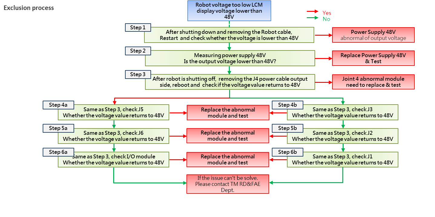
- Robot voltage error
- Camera connection error
- Controller Digital IO error
- Joints error
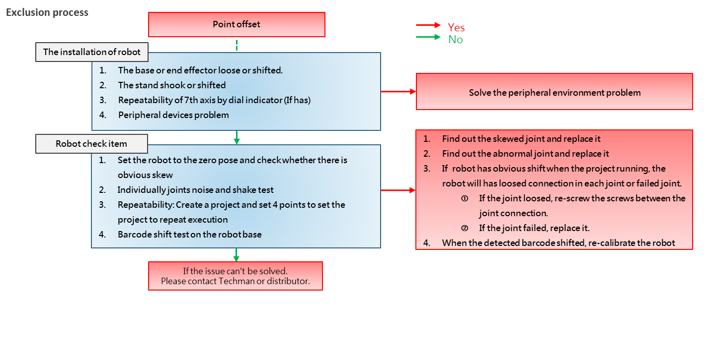
- Point offset
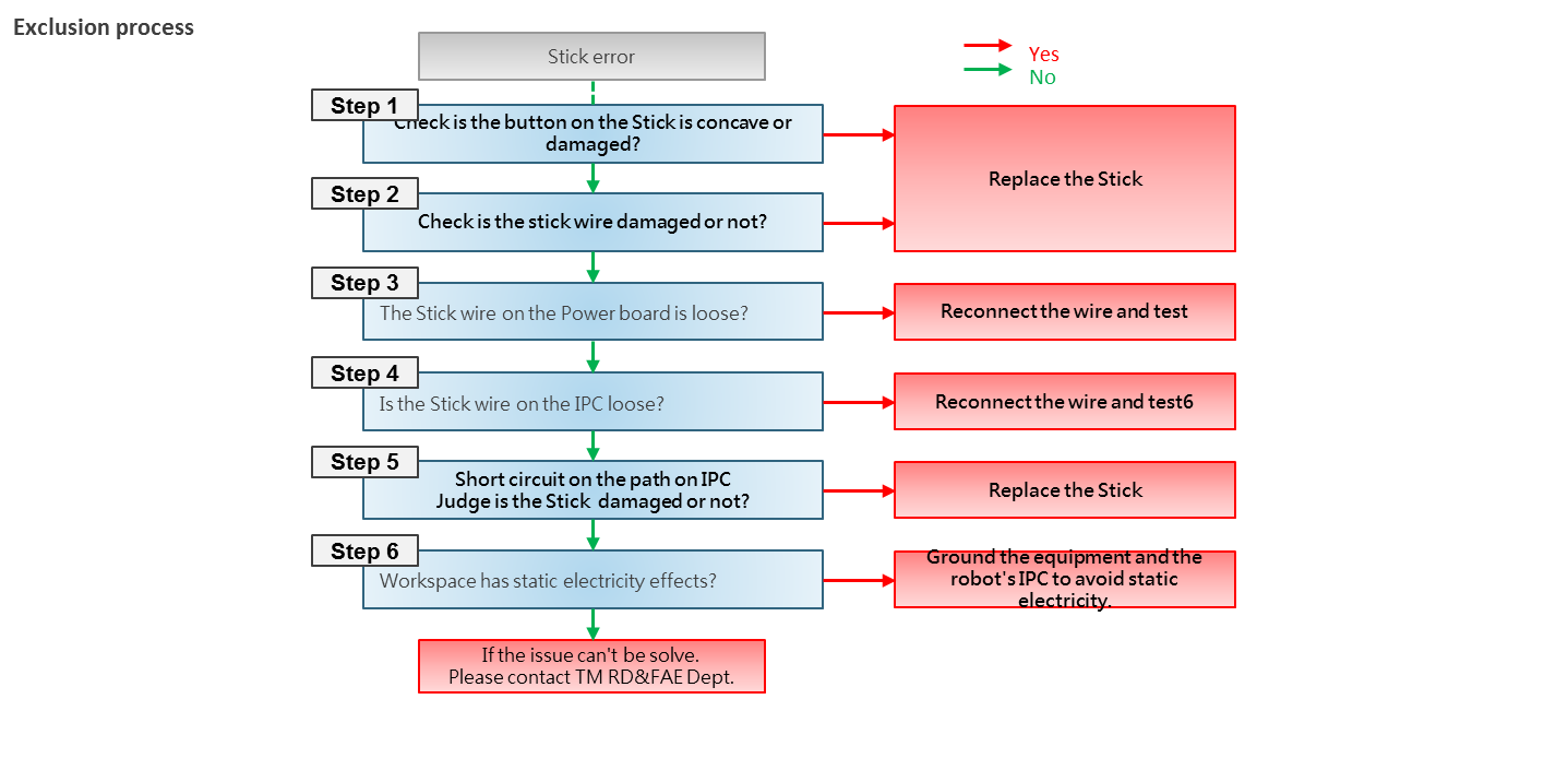
- Stick error
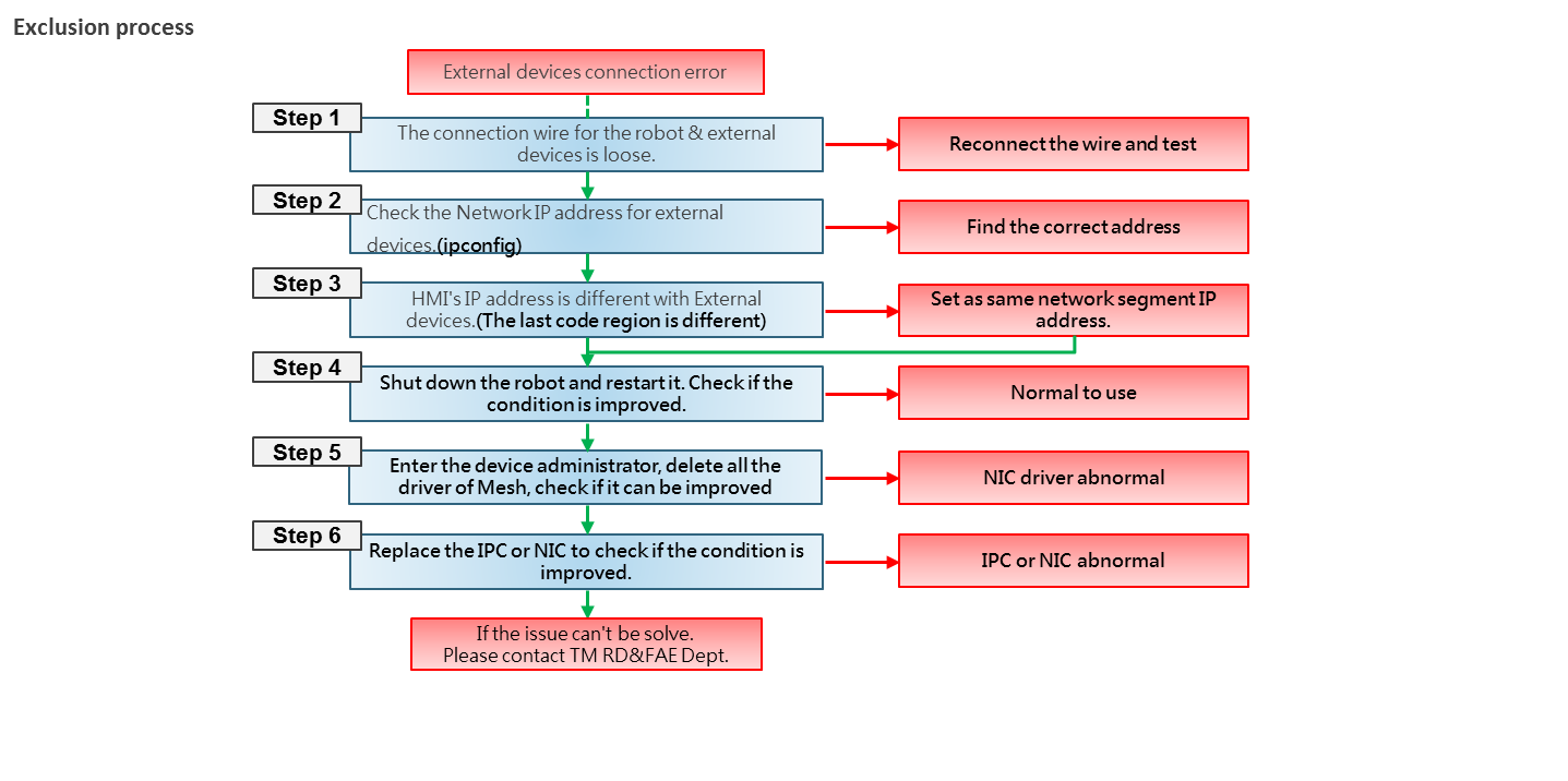
- External devices connection error
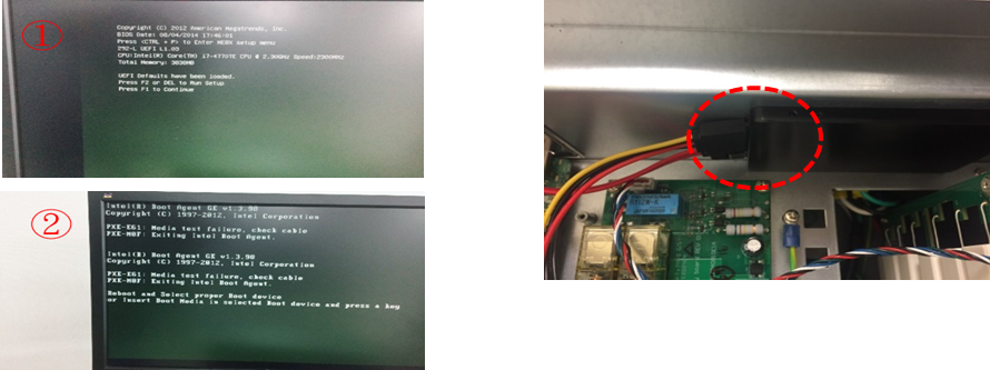
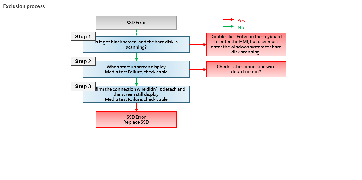
- SSD Error
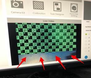
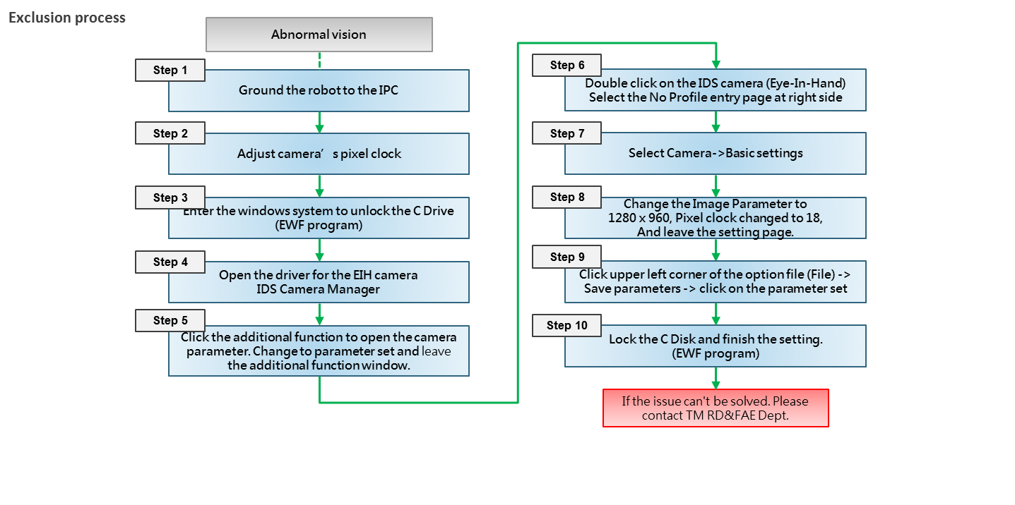
- Vision error
- Singularity of Robot
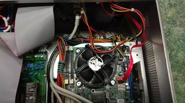
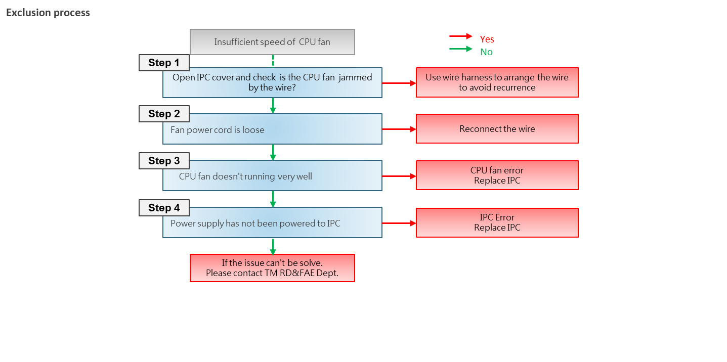
- Insufficient speed of CPU fan
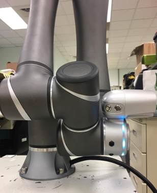
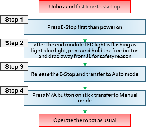
- New robot unboxing and first time to start up
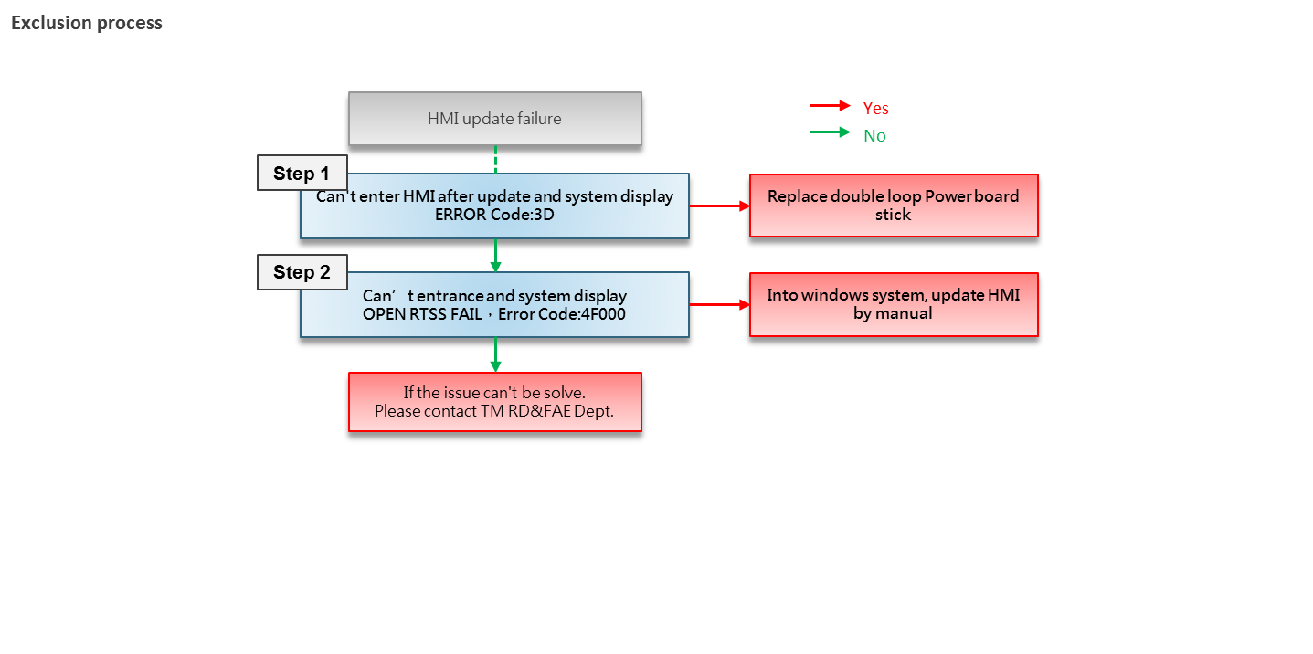
- HMI update failure
- Project open failure
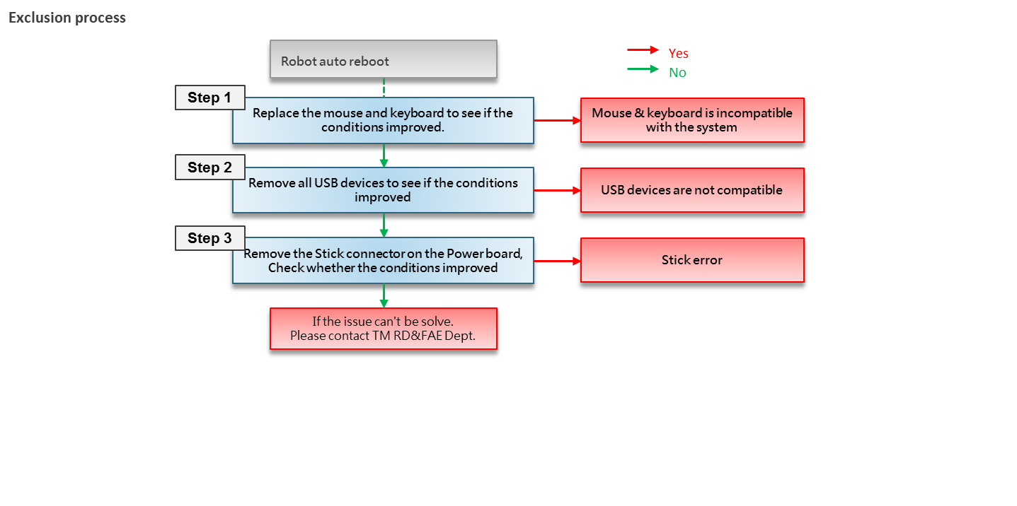
- Robot auto reboot
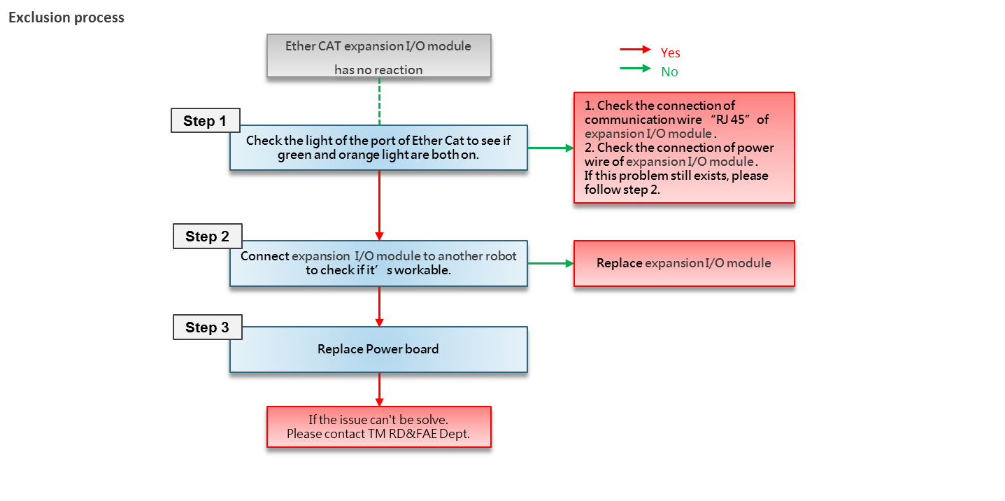
- Ether CAT expansion I/O module has no reaction
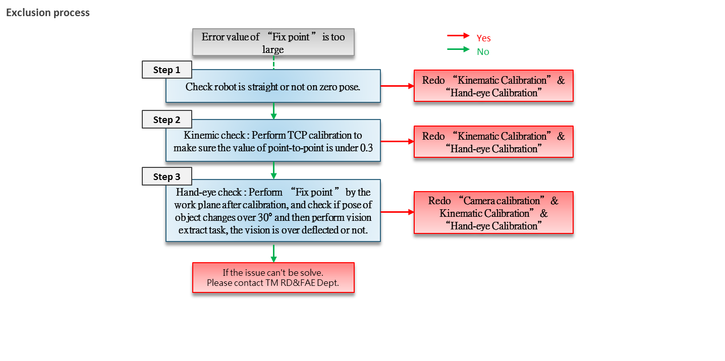
- Error value of “Fix point ”is too large
Control box can not start up #
Robot connection error #
Robot voltage error #
Camera connection error #
Controller Digital IO error #
| Case description | ||
| This section describes possible faults and suggested actions for each fault when Controller Digital IO error. | ||
| Result | ||
| There is delay or no respond on the signal output in the IPC. | ||
| Possible reason | Common error code | |
| The following are possible symptoms of IPC that cannot be start up::
1)DO’s external device, whose current value is higher than 100mA, causing the IO circuit to burn out 2)The leakage current between the circuits of the IPC IO connected to the external device The maximum drive current per channel is 300mA for TM5A/TMAA and 100mA for TM5. If the load exceeds maximum drive current, a relay should be used to drive it. |
NA | |
Joints error #
Point offset #
| Case description | ||
| This section describes possible faults and suggested actions for each fault when the point offset. | ||
| Result | ||
| Project’s points offset due to the collision | ||
| Possible reason | ||
| The following are possible symptoms of point offset:
1)The peripheral environment problem. 2)The joint had loosed or failed. 3)The robot had collision. |
||
| Attention | Techman suggests the customer to verify the joint function every time when collision happened, and estimate to replace the joint while TM judge the joint is damaged.
After trouble shooting, if the collision was caused by project running, please check the project flow as below: a)IO timing b)Flow logic c)Communication timing d)point blending setting |
|
Stick error #
External devices connection error #
| Case description | ||
| This section describes possible faults and recommended actions for each fault when the external device is connected abnormally. | ||
| Result | ||
| The Robot disconnected to the external camera, PC, communication connection device , the port position light is not bright or only the monochrome light (orange or green). note: Need to use the port beside USB port of robot. | ||
| Possible reason | Common error code | |
| The following are possible symptoms about electric control box which cannot be connect to another equipment:
1)The connection wire for the robot & external devices is loose. 2)Incorrect Network IP address for external devices. 3)HMI’s IP address is different with External devices. 4)NIC driver abnormal 5)IPC or NIC abnormal |
NA | |
SSD Error #
Vision error #
Singularity of Robot #
| Case description | This section describes the robot singular point space and how to prevent it. | |
| Result | When the robot pass the singular, the system will report error code 0X09, 0x14 or position information is disordered, causing the robot move abnormally. | |
| Possible reason | 1.Inner singularity
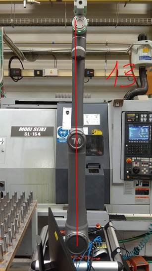
In the inner singularity, the wrist root point is close to cylindrical as shown in below. The definition of cylindrical radius , is distance between center of J1 and J6. Once robot arm close the inner singularity, robot arm will stop and sent out a warning. 2.Extended singularity In the outer singularity, the wrist root point is located at the limit of its work envelope. Namely, J3 is almost in zero degree. Robot arm stop and send out a warning when end-effector beyond working space. Processing steps: While robot arm send out a warning because of inner singularity, user can press the FREE bottom to get rid of warning. Please reconsider the position of the points or change the trajectory between the points. Please avoid the robot trajectory between the points cross the inner singularity 3.Wrist axis singularity In the wrist singularity position, the J4 and J6 line up each other. In this case, these joints will try and spin 180 degrees instantaneously. There is an infinite number of possible for J4 and J6 with identical axis angle. Once situation mentioned occur, robot arm will stop and send out a warning Processing steps: While robot arm send out a warning because of wrist axis singularity, user can press the FREE button to get rid of warning. Try to move the robot along z-axis in tool base when J4 and J6 with identical axis angle will cause wrist axis singularity. The picture below shows an example to prevent wrist axis singularity. |
Common error code
0x00000009 0x00000014 0x0000FF05 |
Insufficient speed of CPU fan #
New robot unboxing and first time to start up #
HMI update failure #
Project open failure #
Robot auto reboot #
Ether CAT expansion I/O module has no reaction #
| Case description | ||
| This section describes possible faults and recommended actions for each fault when Ether CAT expansion I/O module has no reaction. | ||
| Result | ||
| Ether CAT expansion I/O module has no reaction, and HMI shows 0x00000050 | ||
| Possible reason | Common error code | |
| 1)Socket of Ether CAT on Power control board was broken.
2)External equipment was failed. 3)Connection for external equipment was failed. |
NA | |


