TMflow 軟體版本 : 2.20或以上之版本皆適用
TM 手臂硬體版本 : HW 3.2或以上之版本皆適用
注意事項:不同版本的軟體可能會呈現不同結果
硬體取得 #
如何選擇 相機、鏡頭、IO 觸發線 #
飛拍功能需透過高效能工業相機以及適當的鏡頭才可執行,建議的硬體規格如下:
相機選擇: 需搭配外接相機使用, 僅支援 TM Plug&Play 的 Basler 全域快門 (Global Shutter) 相機.
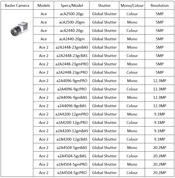
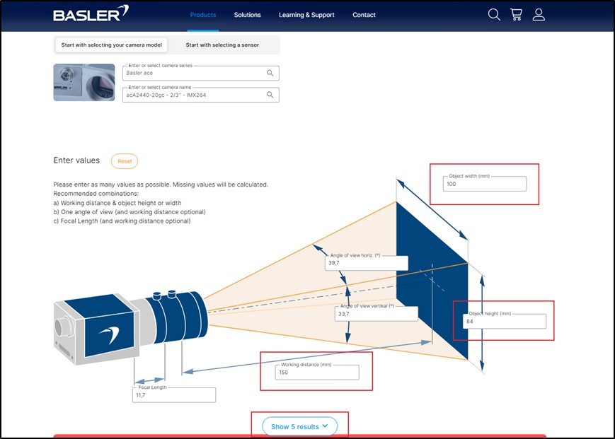
鏡頭選擇 : 請參閲 Basler 官網的 鏡頭選擇頁面 , 並依據工作距離與視野範圍選擇合適的鏡頭。
IO 觸發線連接器
Ace 與 Ace 2 相機使用不同的 IO 觸發線連接器。如需購買對應的線材,請至 Basler 官網進行選購。
上述所提的相機與鏡頭選擇,也可參考技術文件: 相機、鏡頭與光源的選擇方式
選擇光源與光源控制器 #
光源有多種選擇,本文所使用的光源來自 3AM
光源 : #
不同的應用情境需採用不同類型的光源,詳請參考技術文件: 相機、鏡頭與光源的選擇方式
光源控制器:
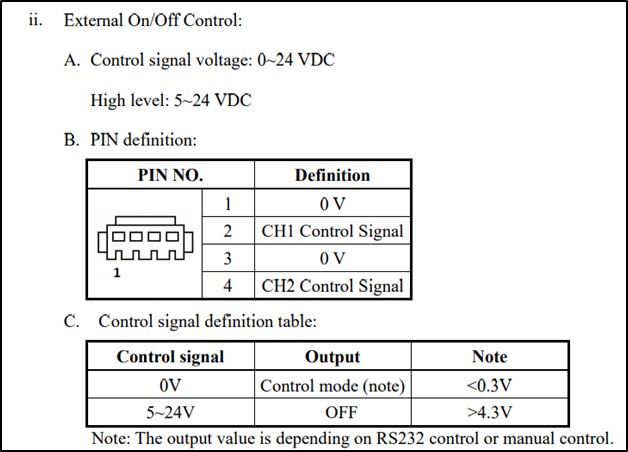
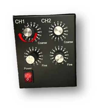
若需要將光源與相機拍攝動作同步,調光器必須支援外部 IO 控制。例如, 3AM 的 GLC-PD24V30W-2CH 調光器具備外部 IO 控制設定,詳細內容可參閱其使用手冊(如下圖所示)。
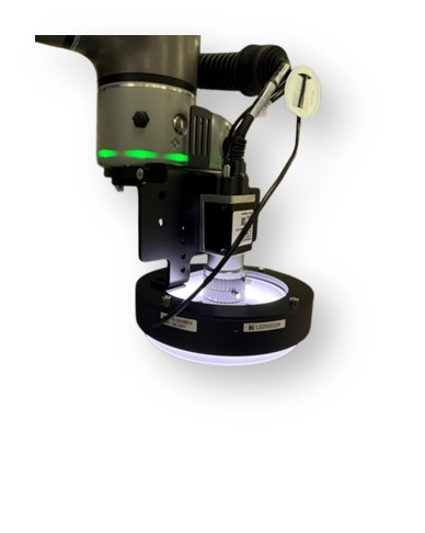
將相機與光源安裝至機器人 #
您可以使用達明機器人提供的 相機支架 , 將相機與光源安裝到機器人上。在光源的安裝部分,由於各款光源的外型相異,可以依據相機支架的孔位,自行設計適用於該光源的安裝轉接件。
觸發線配置 #
在進行飛拍時,您可以選擇是否讓光源僅在相機拍照時亮燈,或是在機器人觸發相機期間持續亮燈。將光源與相機同步控制,能延長光源壽命,並最大程度降低強光對周圍人員的影響。
以下介紹兩種情境:
- 機器人觸發相機,不控制光源:光源持續亮燈。
- 機器人觸發相機,由相機控制光源:光源僅在拍照瞬間亮燈,其餘時間保持關閉。
Basler 相機包含 ace 與 ace 2 系列,兩者所需的觸發線與配線方式不同。以下章節將分別說明 ace 與 ace 2 的觸發線與配線方式。
機器人僅觸發相機,不控制光源 #
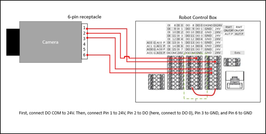
在此情境中,相機不需觸發光源,因此僅需配置機器人觸發相機拍攝的線。
Ace 相機 #
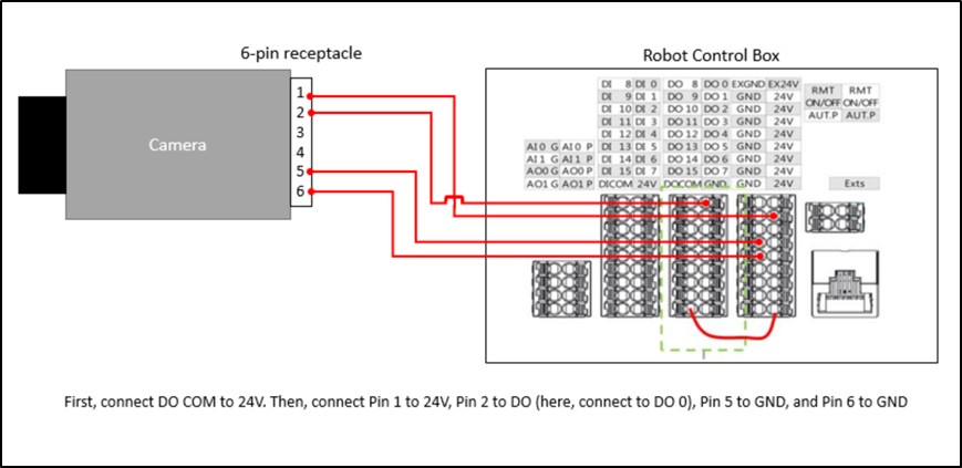
根據電控箱配線圖(請參考相關的達明機器人說明書)及 Basler 相機的輸入端,完成機器人觸發相機的設定,如下方配線圖所示:
Ace2 相機 #
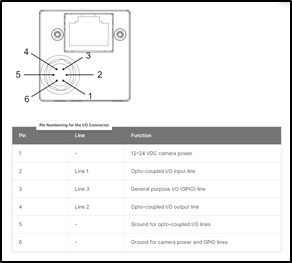
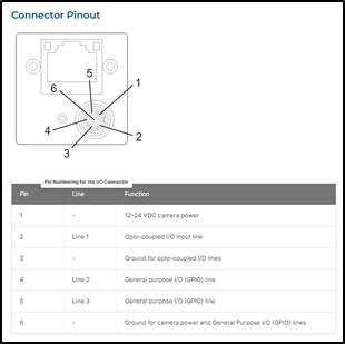
- 觸發線的接腳說明如下。
- 相機端的機器人輸入訊號觸發設定。

根據電控箱配線圖(請參考相關的達明機器人說明書)及 Basler 相機的輸入端,完成機器人觸發相機的設定,如下方配線圖所示:
機器人觸發相機,相機控制光源 #
在此應用情境中,除了需設定機器人觸發相機的配線外,還需將相機的輸出設定為觸發光源。
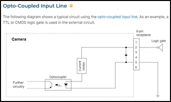
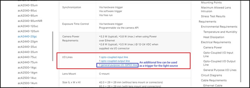
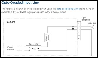
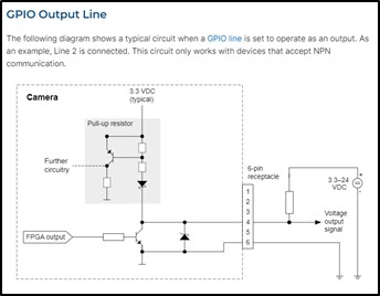
若要在拍攝影像時觸發光源,需至少有兩條 I/O 線路。以下範例以Basler 相機的I/O 線路規格做為參考:
Ace 相機 #
- 觸發線的接腳說明如下:

- 相機端的機器人輸入訊號觸發設定

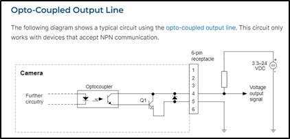
- 相機端同步觸發光源的配線設定
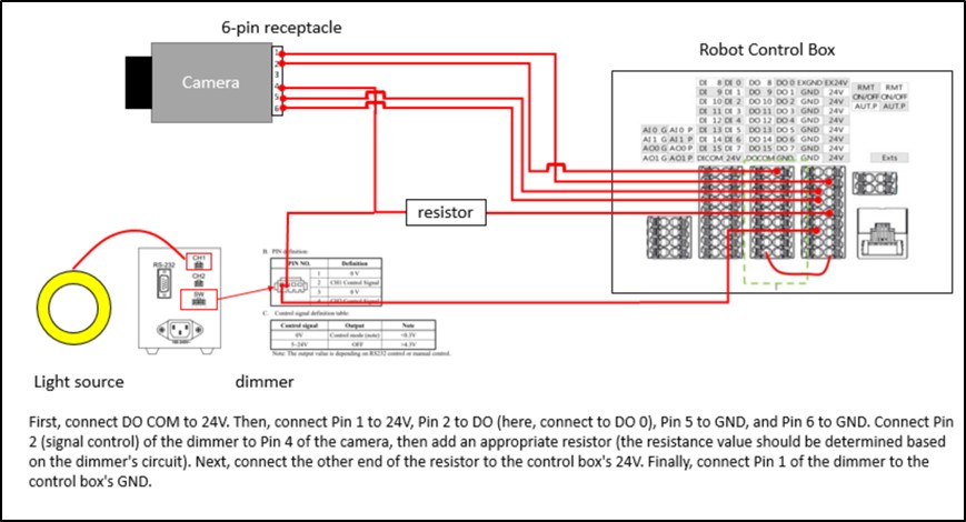
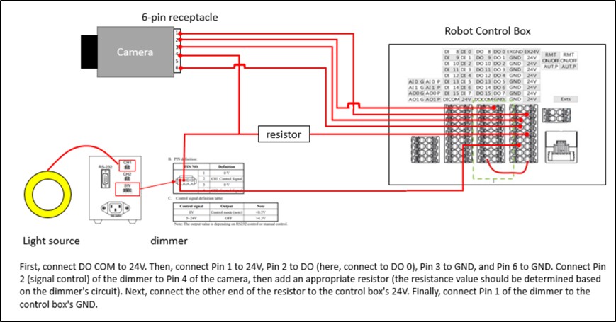
根據電控箱配線圖(請參考相關的達明機器人說明書)及 Basler 相機的輸入端,需將相機連接至光源控制器的外部 I/O。下方配線圖說明如何完成機器人觸發相機的設定。
Ace2 相機 #
- 觸發線的接腳說明如下:

- 相機端的機器人輸入訊號觸發設定。
- 相機端同步觸發光源的配線設定。
根據電控箱配線圖(請參考相關的達明機器人說明書)及 Basler 相機的輸入端,完成機器人觸發相機的設定,如下方配線圖所示:
注意事項:
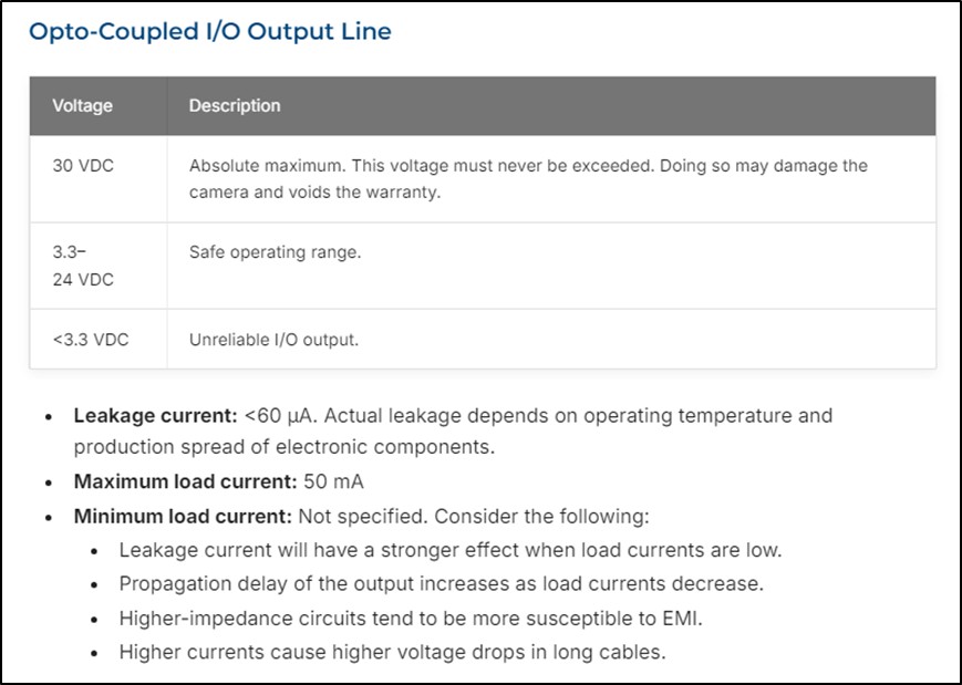
請依據Basler相機的最大電流限制(50mA)選擇電阻。若電控箱為 24V,則電阻值不得低於 24V / 0.05A = 480Ω。
如需更詳細的資訊,請造訪 Basler 官方網站 :
Pylon 設定 #
若需同步觸發光源,必須透過 Pylon 軟體設定,並將光源相關參數寫入相機。
請將相機連接至電腦,並啟動 Pylon。安裝與使用說明請參考Basler網站。
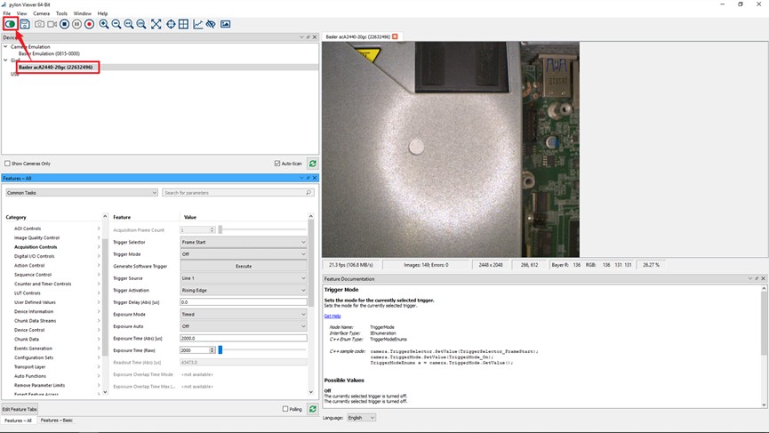
接著,進行光源同步設定。點擊Digital I/O Controls,將 Line Selector 設為 Line 2、Line Mode 設為 Output、Line Source 設為 Exposure Active。

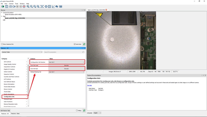
最後,將所有參數儲存至 User Set 1,此設定將儲存在相機內。
硬體設定 #
1. 開啟TMflow、連接相機。
請依照達明機器人使用手冊所述的步驟進行設定。
2. 點擊配置 > 視覺設定,選擇飛拍相機,曝光時間的初始值設為3000µs。
3. 將光源控制器亮度設為100%。
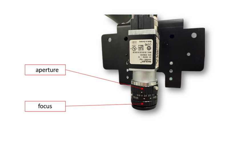
4. 調整光圈,確保景深符合檢測需求。
5. 調整焦距,確保目標物特徵可被清晰、均勻拍攝。
注意事項:
若影像亮度不足,請調整光源或增益:
- 使用亮度更高的光源或提高光源控制器的輸出值。
- 調整增益可提升亮度,但可能產生影像雜訊。
若仍無法達到足夠亮度,可將曝光時間提升至 3000~5000µs 區間,但可能會增加動態模糊的風險。
6. 校正內部參數
詳細校正步驟請參閱技術文件: Notice on External Camera Calibration
軟體設定 #
本節說明如何在 TMflow 中設定飛拍功能。請注意,下列設定以特定硬體架構為基礎。詳細的設定說明,請參考技術文件:
How To Use Flying Trigger Node – Take server inspection as example


