- IPC inspection task description
- Shooting screen adjustment
- How to select the ROI and image collection
- Image collection instructions
- Image collection instructions - Is equipped with filter ring
- Image collection instructions -Is the plugin actually inserted
- Image collection instructions-whether there is a screw in the screw hole_top shot of the IPC
- Image collection instructions - whether there is a screw in the screw hole_side shot of the IPC
- Image collection instructions - whether the cable is connected correctly
- Image collection instructions - image storage method
- Train models with TM AI+ and import AI models into robot testing
- Tip
The example of this article applies to the following conditions :
Hardware requirements :
- Advantech AIR 300 Training server
- TM Robot (HW 3.0 and above version)
- IPC
- Polarizer
- Suitable working enviroment
- TM calibration plate
Software requirements :
- Dongle with TM AI license
Version requirements:
- TMflow version: 1.88.2200(If you are using the above version, you need to match the relevant version of TM AI+ Training Server )
- TM AI+ Training Server 2.12.2200(If you are using the above version, you need to match the relevant version of TMflow)
IPC inspection task description #
Inspection Process : #
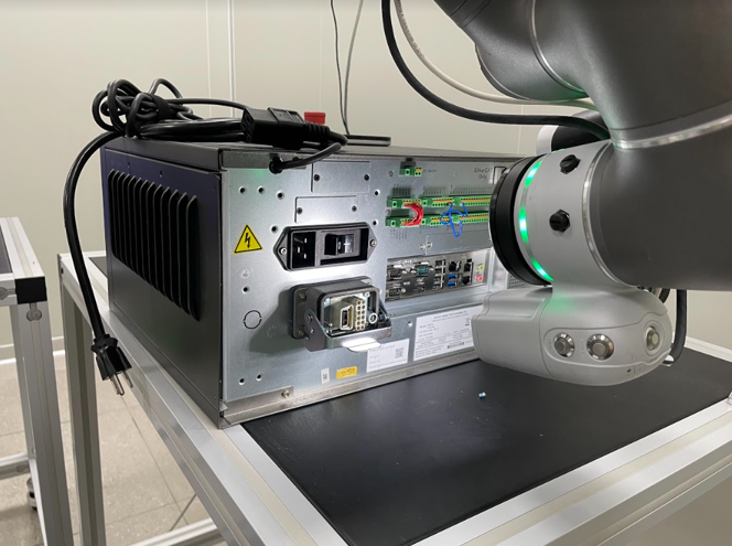
Use the display panel of the IPC for Pattern matching positioning, and move the robot to the inspection area to inspect the following items in order
1.Is the filter ring installed on the power line
2.Whether the cable is actually inserted into the slot
3.Are the screw holes screws
4.Is the cable alignment method correct
Shooting screen adjustment #
Place the IPC in the working plane #
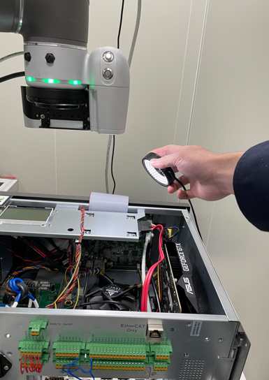
Determine the working enviroment is fixed, the IPC placed on the work plane, adjust the shooting angle, and open the light source, you can replace the polarizer to avoid reflections that lead to unclear images.
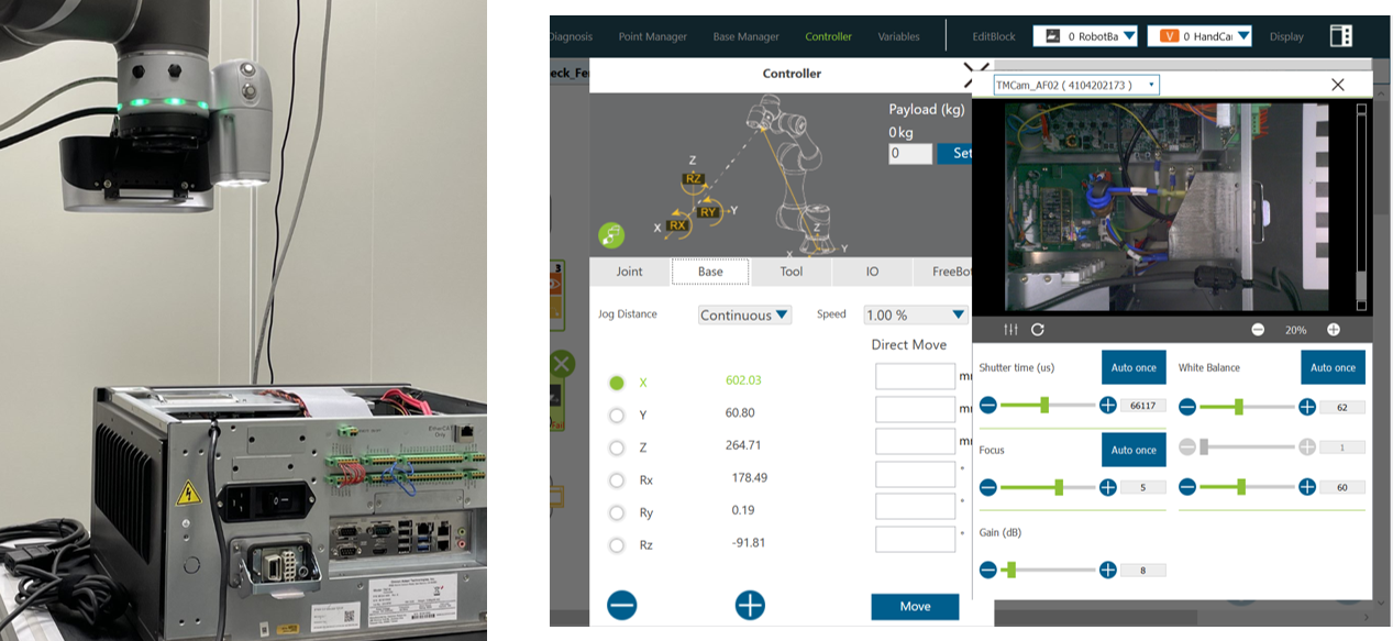
Move the robot to select the shooting area #
Move the robot to the desired location, use the controller to control the movement of the robot, and observe whether the object to be detected is within the visible range through Vision.
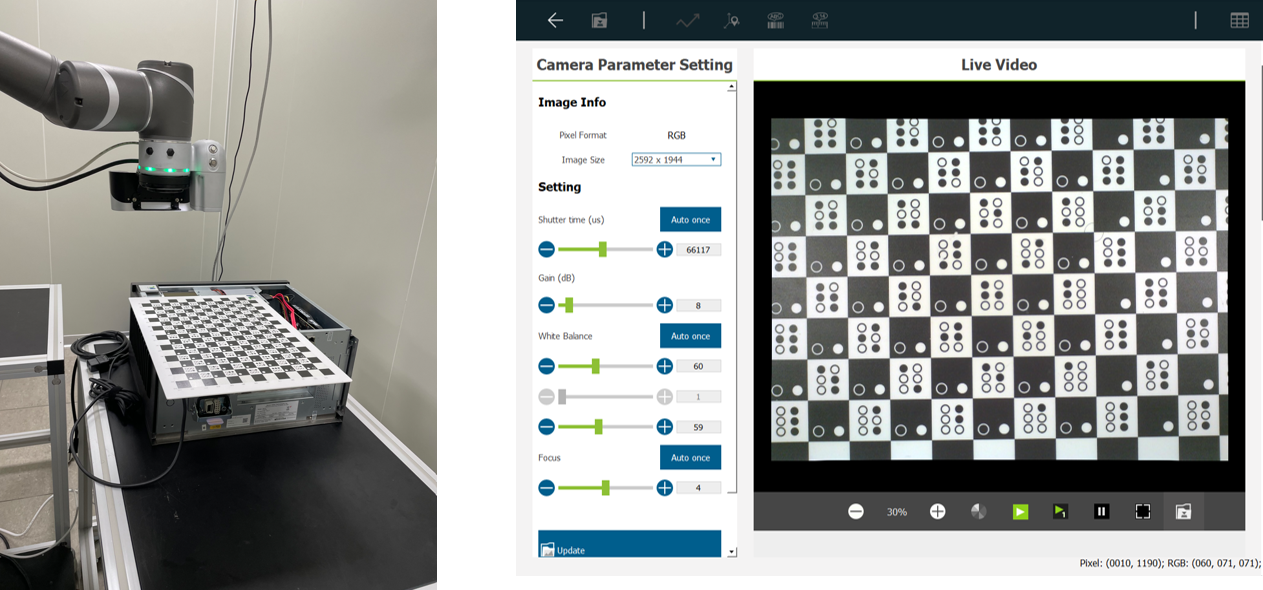
Shooting images and parameter adjustment #
Determine the field of view to be detected, place a TM calibration plate, open the light source (it is recommended that the use of polarizers to avoid reflections leading to unclear shooting), adjust the parameters of the camera.
How to select the ROI and image collection #
Image collection instructions #
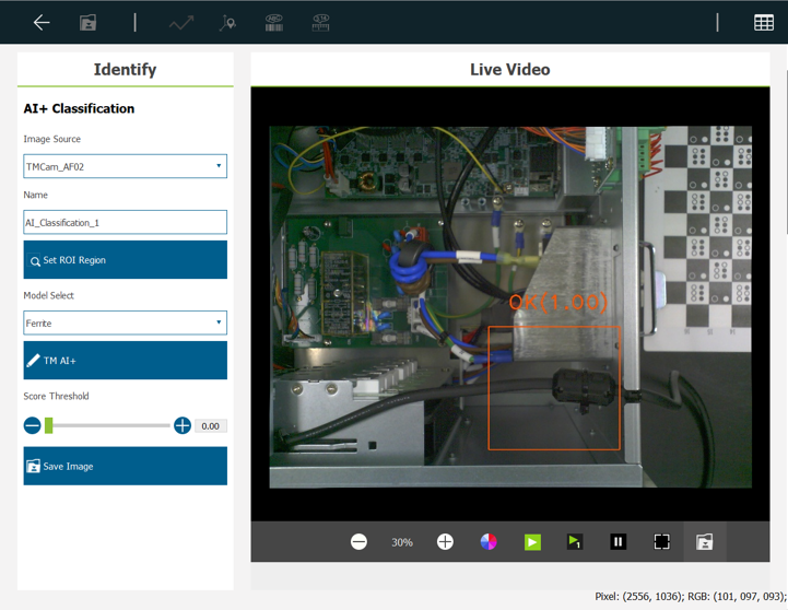
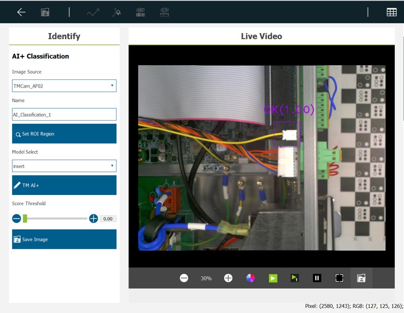
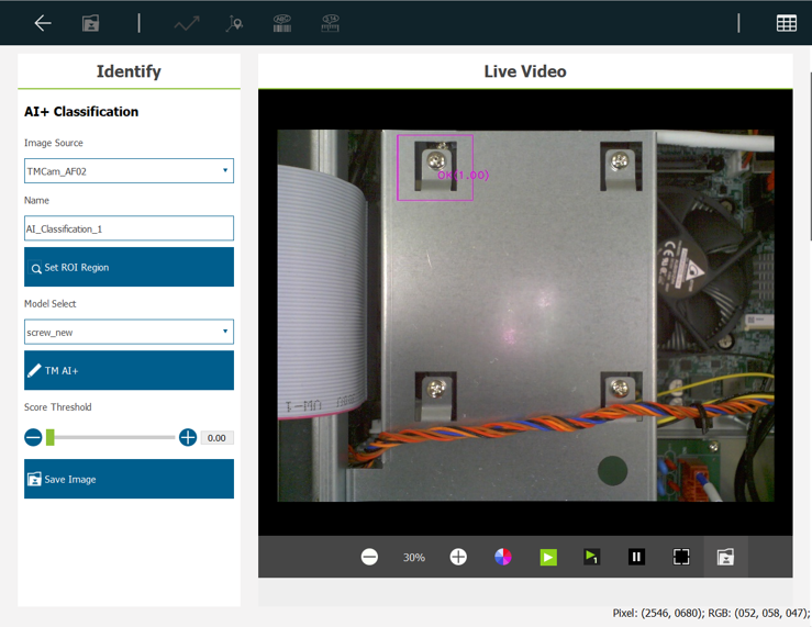
When performing AI Classification, the entire screen is not captured, but the features within the detection range must be selected. The following examples show how to select ROI and choose the images to be captured for the following detection contents.
- Is equipped with filter ring
- It is “OK” to equip with filter ring.
- “NG” without magnetic ring equipped.
- Is the plugin actually inserted
- There is indeed inserted as “OK”.
- Not really inserted or not inserted as NG.
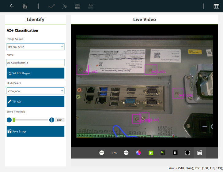
- Whether the screw hole has locking screw attached
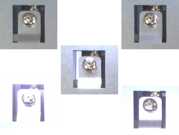
- Locking screw for “OK”.
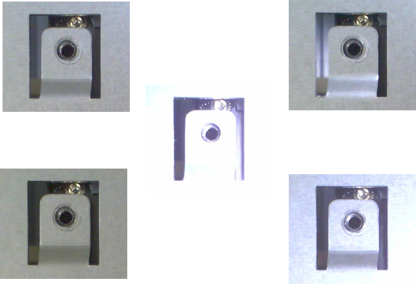
- Not locked with screws for “NG”.
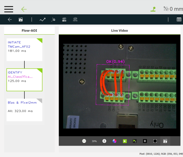
- Is the cable alignment method correct
- Cable on and correct is “OK”.
- Cable not connected as “NG”.
- Cable interleaved as “CROSS”.
Image collection instructions – Is equipped with filter ring #
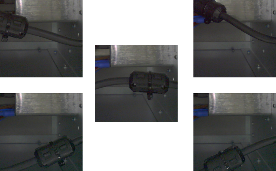
Attach the filter ring first. Because the filter ring is attached to the power line, there will be a certain range of movement. When making a frame selection for the filter ring, the possibility of moving the filter ring must be considered as much as possible. Refer to the following figure
When collecting OK situations, various possibilities of the movement of the filter ring must be considered, so you can try to move the filter ring more to create various possibilities of the appearance of the filter ring . To ensure that there is enough information, it is recommended to collect about 30 images. The demonstration is as follows.
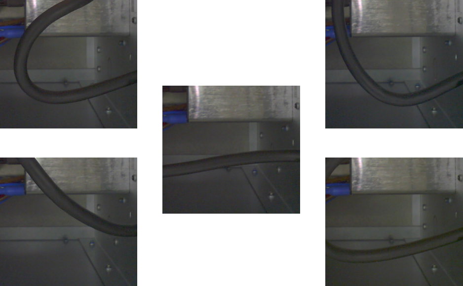
When collecting NG situations, various possibilities of the power cord must be considered, so you can try to create various possibilities of the power cord. In order to ensure enough information, it is recommended to collect about 30 images, as shown below.
Image collection instructions -Is the plugin actually inserted #
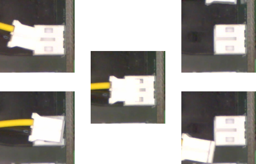
Since the position of the plug-in is fixed, the plug-in screen must occupy most of the ROI screen, so as to avoid being affected by the background factors and affecting the AI judgment.
When collecting OK situations, since the plug-in changes little, you can try to change the angle of the wire head. It is recommended to collect about 30 images, or change the ambient light source to adapt to various environmental changes. If you want to change the ambient light source, it is recommended to collect more images to increase the information for AI learning.
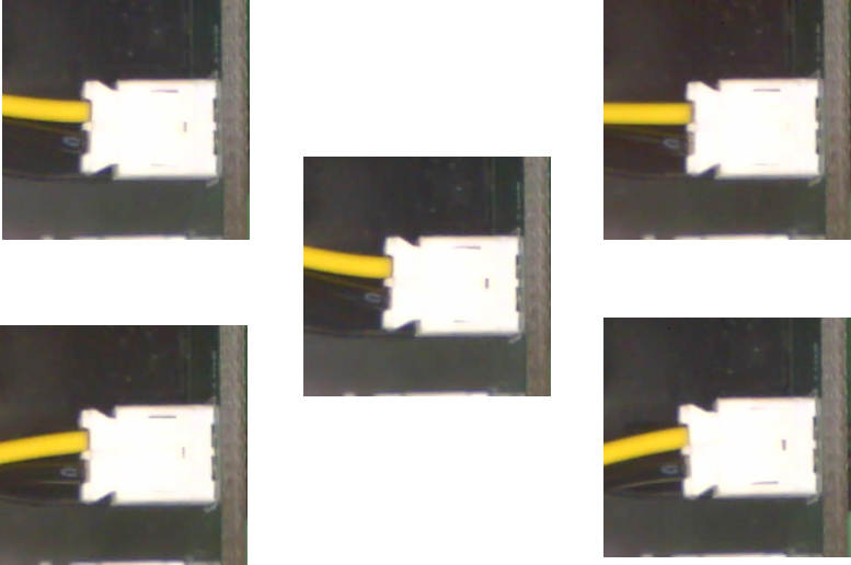
When collecting NG cases, you need to collect more possibilities of incomplete insertion, to prevent AI from confusing the cases that are almost inserted and fully inserted. At the same time, you also need to consider the possibility of no insertion at all. It is recommended to collect about 30 images.
Image collection instructions-whether there is a screw in the screw hole_top shot of the IPC #
When selecting the screw hole, the hole position must also occupy more than half of the ROI. Considering that there are various angles or lighting problems when shooting screws, the selection range should not be too narrow, so that it can cope with different situations.
Since the state of the screw locking the screw does not change much, and the background is mostly metal surface, we can create additional light sources to increase the information of various environmental changes.
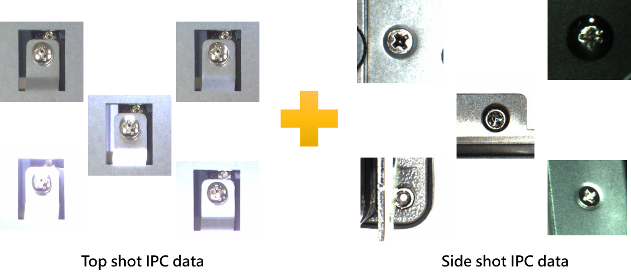
The following shows the situation of collecting OK images. It is recommended to collect about 30 images. You can see that each image is affected by different light and shadow.
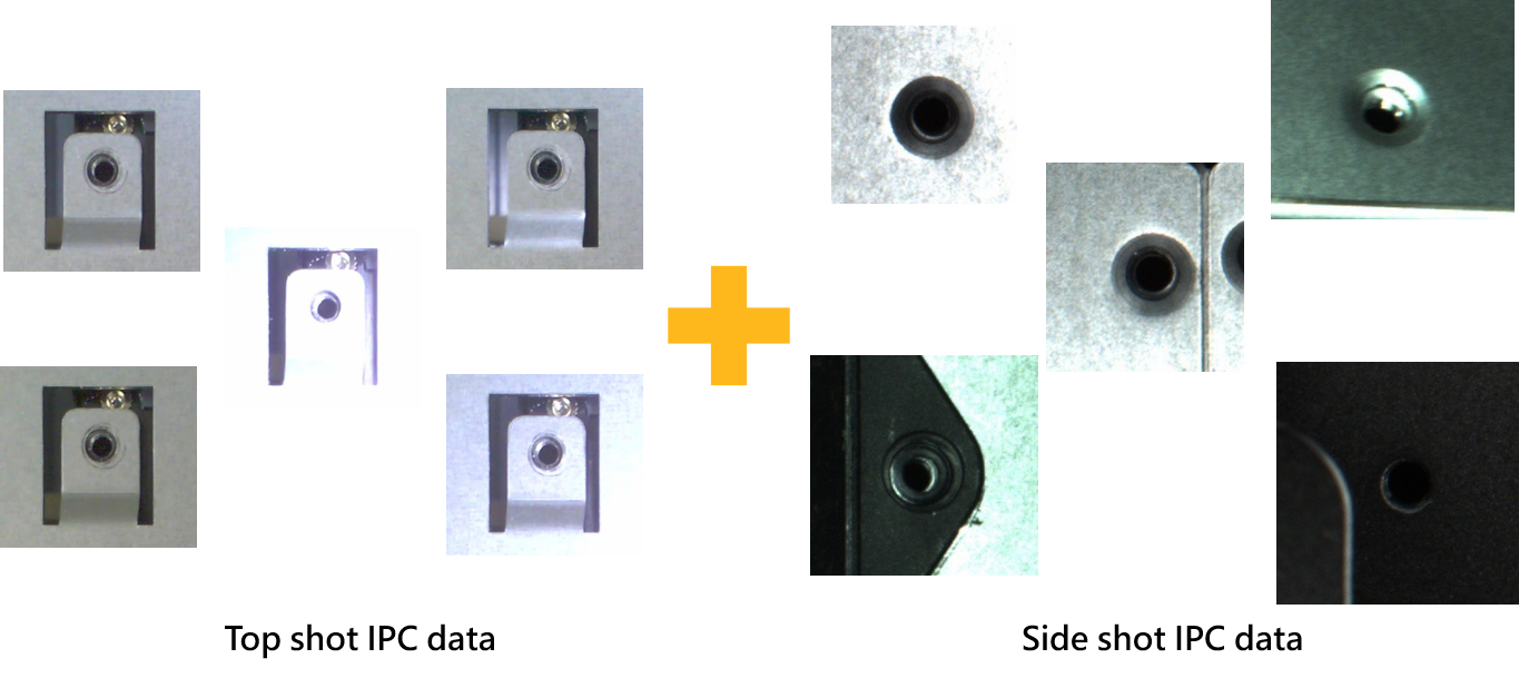
Whwn collecting NG images, you can also refer to the way of collecting OK images. It is also recommended to collect about 30 images and consider the influence of different light soutces.
Image collection instructions – whether there is a screw in the screw hole_side shot of the IPC #
After taking the upper screw, we move the robot to the side of the IPC and check whether the side screws are locked. Since there are various changes in the side shot, you can also create extra light sources to simulate different situations.
The screw hole should also occupy more than half of the ROI range, and the screw hole should be as close to the center of the ROI as possible, to prevent reflection from causing AI information misjudgment.
Similarly, when collectng OK situations, you can consider different light sources. In order to make AI able to judge more screw, you can add the situation of shooting the upper control box to this situation for training. It is recommended to collect about 30 images, combined with the situation of the upper control box, to cope with various situations.
And when collecting NG situations, you can also add the situation of shooting the upper control box to this situation for training. It is recommended to collect about 30 images, combined with the situation of the upper control box, to cope with various situations.
Image collection instructions – whether the cable is connected correctly #
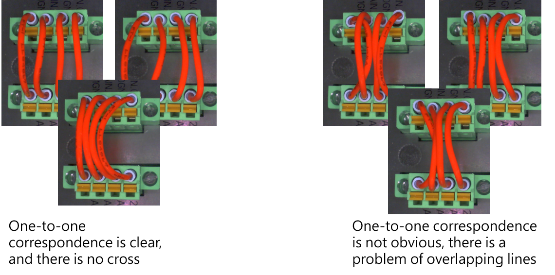
The purpose of this task is to confirm whether the cable is properly inserted and inserted in the correct position, and therer should be no wrong or unplugged situations. The entire cable should also occupy most of the ROI range, and try not to have redundant backgrounds that affect AI judgment. We divide the cable into three situations for image collection.
- One-to-one correspondence, overlapping lines are also accepted, regarded ad OK
- The cable head is properly inserted, but inserted in the wrong hole, regarded as CROSS
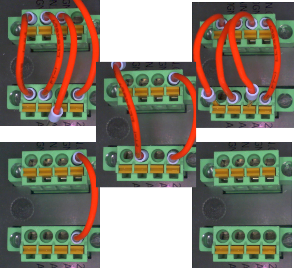
- The cable head is not properly inserted, regarded as NG
Image collection instructions – whether the cable is connected correctly_OK situation
One-to-one correspondence, overlapping lines are also accepted, make sure the cable head is properly inserted, create some opening and closing situations, and create overlapping cable heads, collect about 30 images, the following are all regarded as OK situations.
Image collection instructions – whether the cable is connected correctly_CROSS situation
The cable head is properly inserted, but inserted in the wrong hole, collect the situations of two lines crossing, three line crossing, and four lines crossing, and consider all possible combinations as much as possible. Collect 2 to 3 images for each of the above situations, so a total of about 30 images are collected.
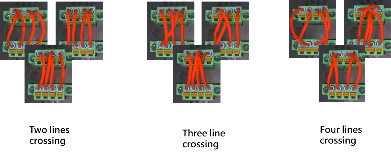
Image collection instructions – whether the cable is connected correctly_NG situation
The cable head is not properly inserted, collect the situations where there may be four unplugged, three unplugged, two unplugged, or even all unplugged, collect about 30 images.
Image collection instructions – image storage method #
There are two main items for storing images (for detailed storage instructions, please refer to the manual)
- Store ROI image in AI Classification
- TM AI+ Training Server Dataset
- TM SSD external hard drive
- Store Source images when running with Vision Job
-
- TM SSD external hard drive
- Network Service
- Save Image Component
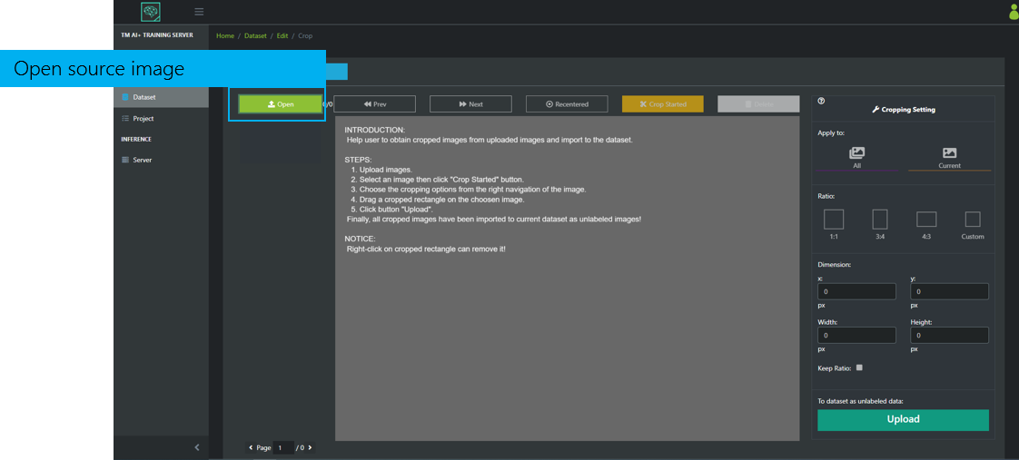
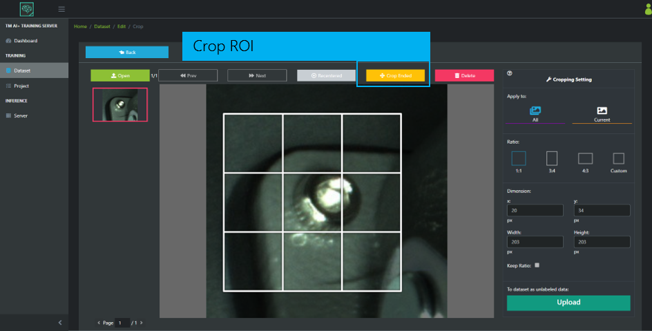
When choosing the second way to store Source images, you can Crop ROI in the Dataset of version 2.12 Training Server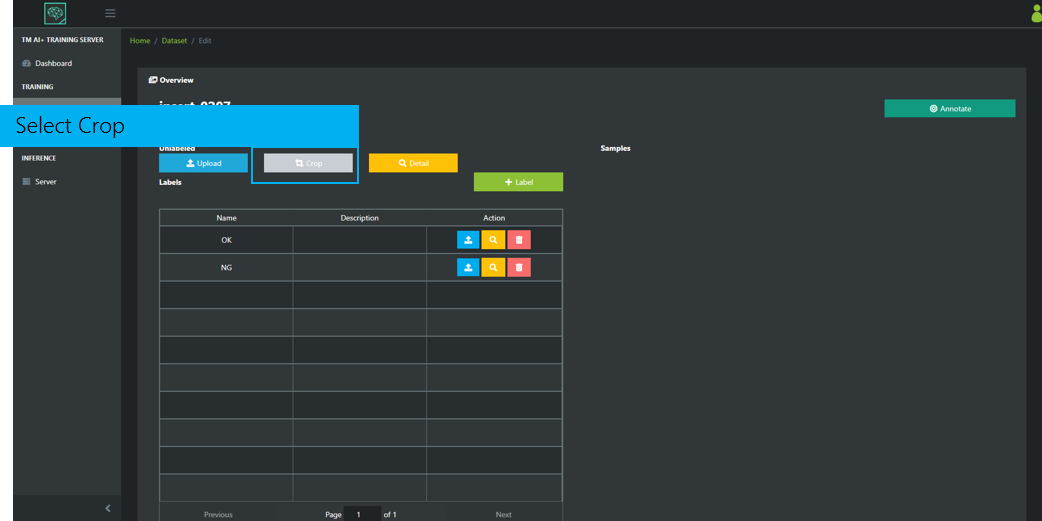
Crop ROI. The ROI will be labeled as unlabeled after the crop.
Train models with TM AI+ and import AI models into robot testing #
TM AI+ operation #
Save the images of the inspection processes above into two datasets, one for OK and another for NG, as shown below.
TM AI+ is built on the company’s internal server. Any device that can connect to the company’s intranet can use TM AI+ through a browser, and there is no restriction on the system for operation. This article uses TM AI+ Training Server 2.12.2200 as an example.
This is the manegerment screen of the Dataset, where we can import our datasets.
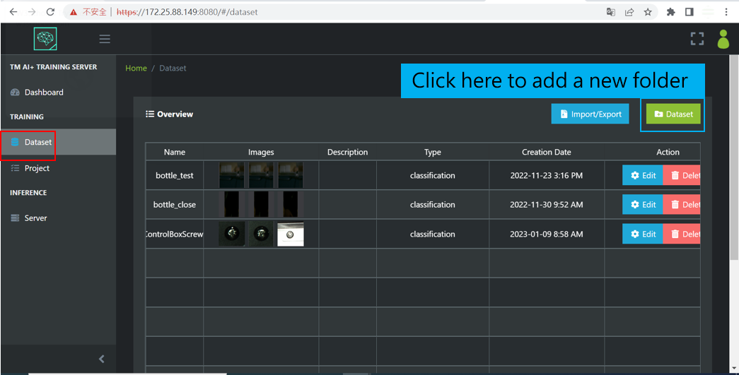
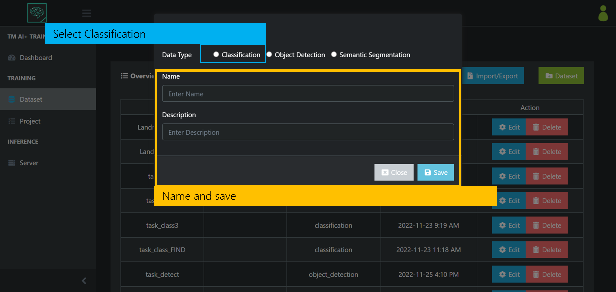
Create a classification dataset.
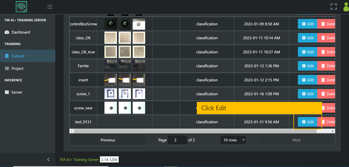
Click Edit to create a dataset.
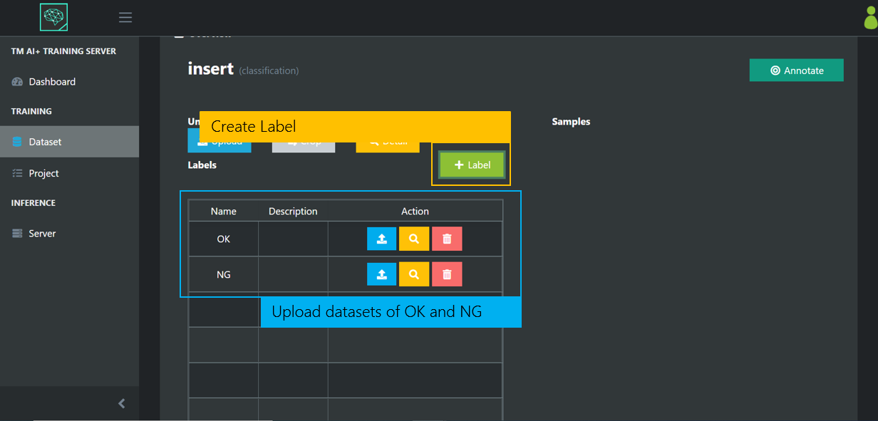
Create labels and upload the corresponding datasets.
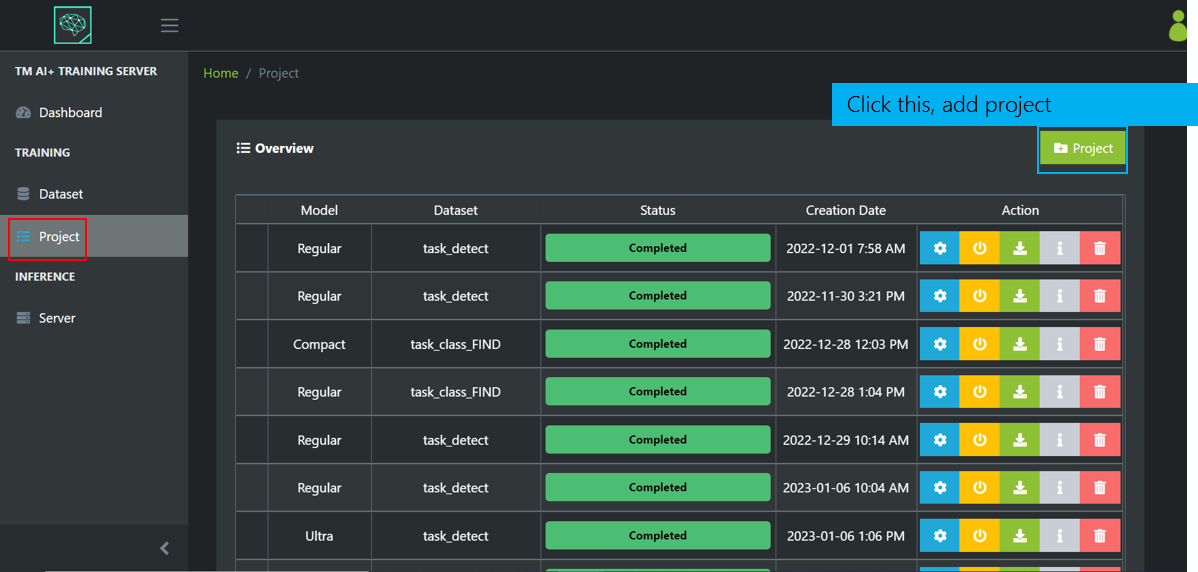
This is the project management screen, where you can create our projects.
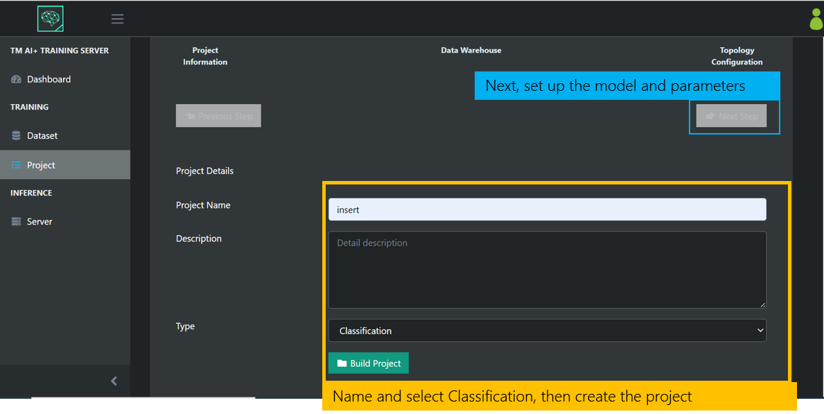
Add a project, name it and select Classification.
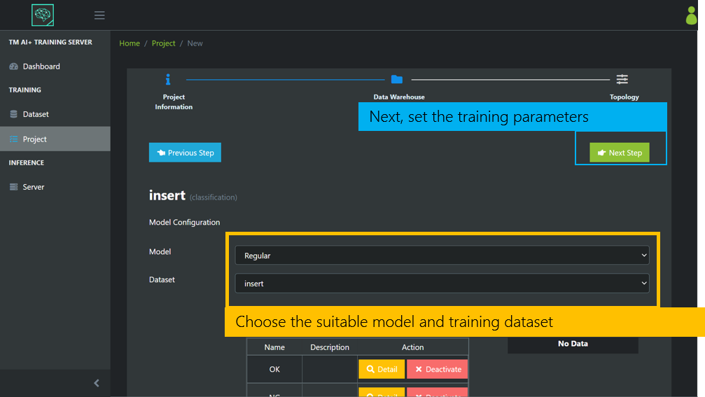
Choose the appropriate model and dataset according to the task scenario.
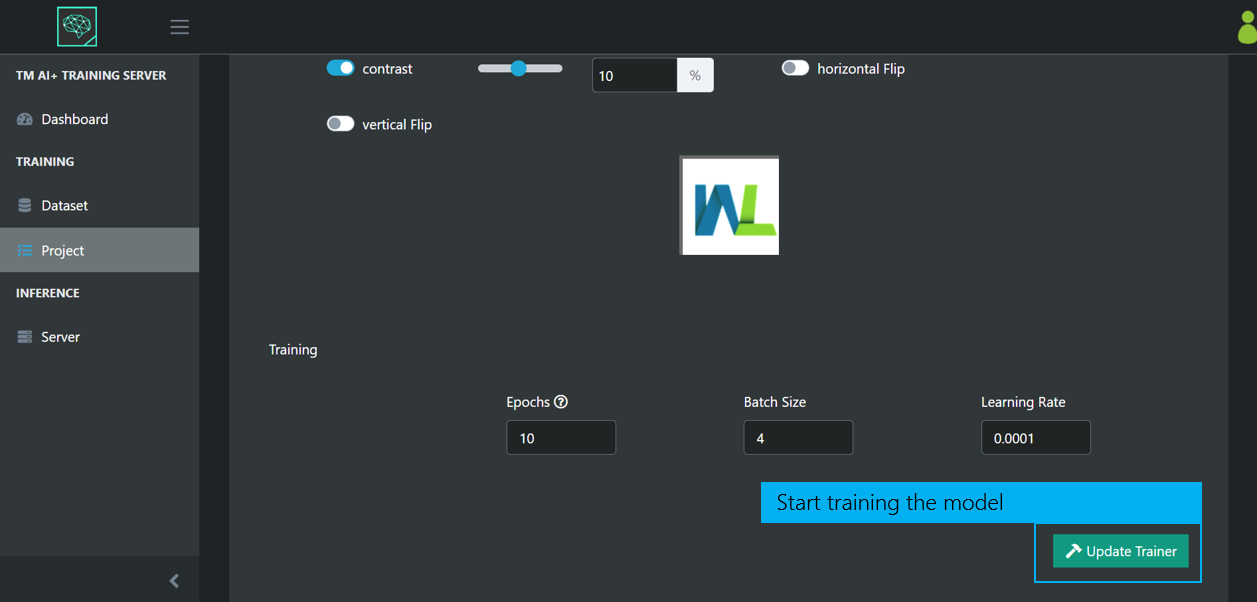
After adjusting the parameters, start training the model.
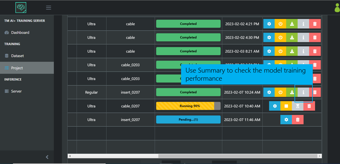
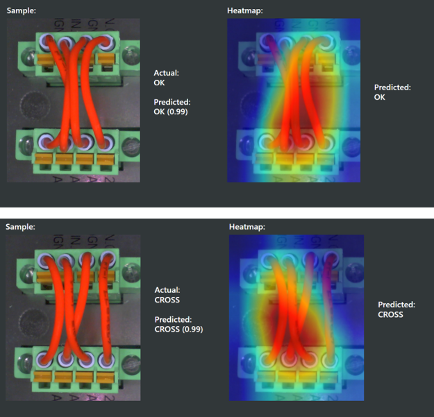
After the training is completed, you can use summary to check the performance of the trained model, and use Heatmap to analyze whether the information learned by AI is the feature we want to compare. Then this article will analyze each detection result and perform analysis.
TM AI+ – Is equipped with filter ring #
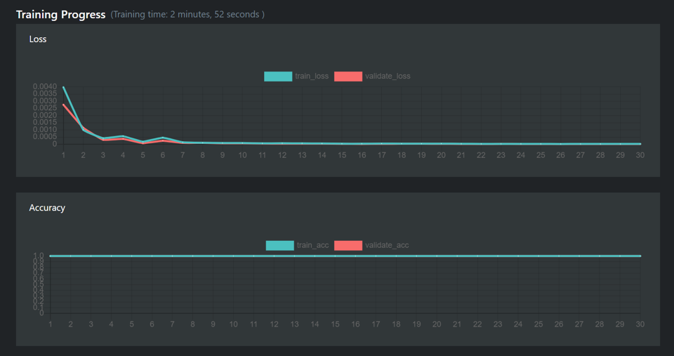
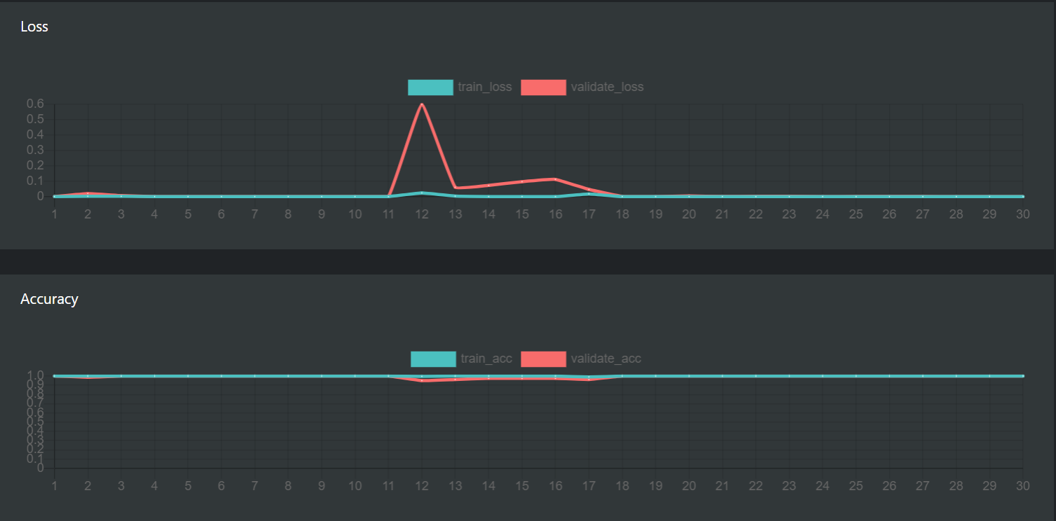
Observing the training progress, the accuracy of each training session is almost 100 percent, indicating that the model for detecting the filter ring is more stable.
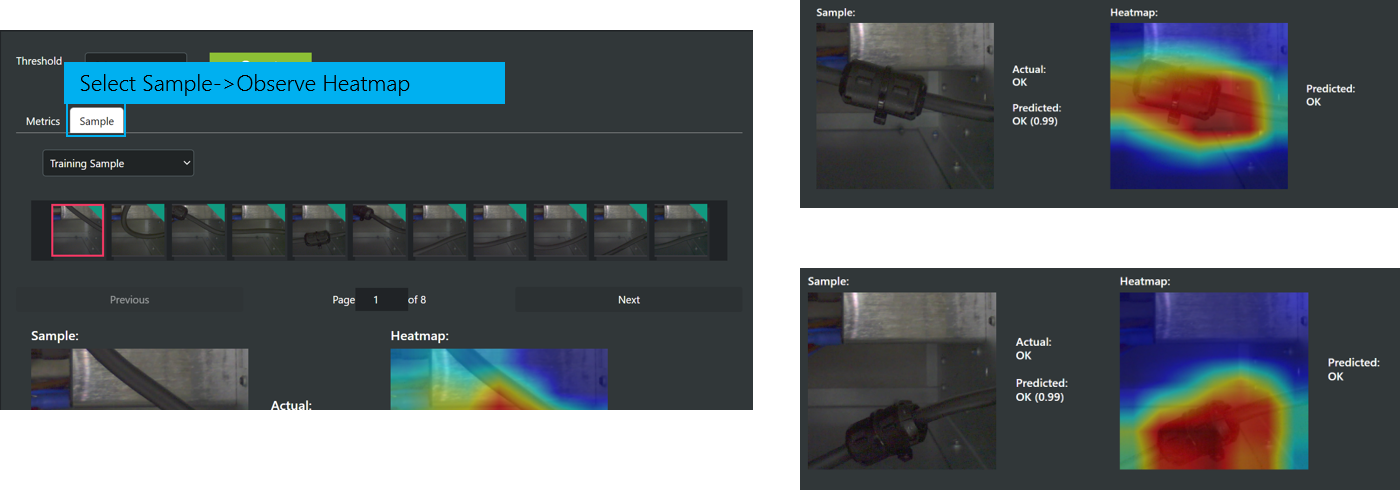
By using the heatmap, we can see that AI has detected the filter ring on the line, indicating that features learned by AI are reasonable. We import this model into the robot for testing, and it can stably distinguish whether there are filter ring.
Then we switch to another robot and environment for testing and it can also stably distinguish, without changing the model.
TM AI+ – Is the plugin actually inserted #
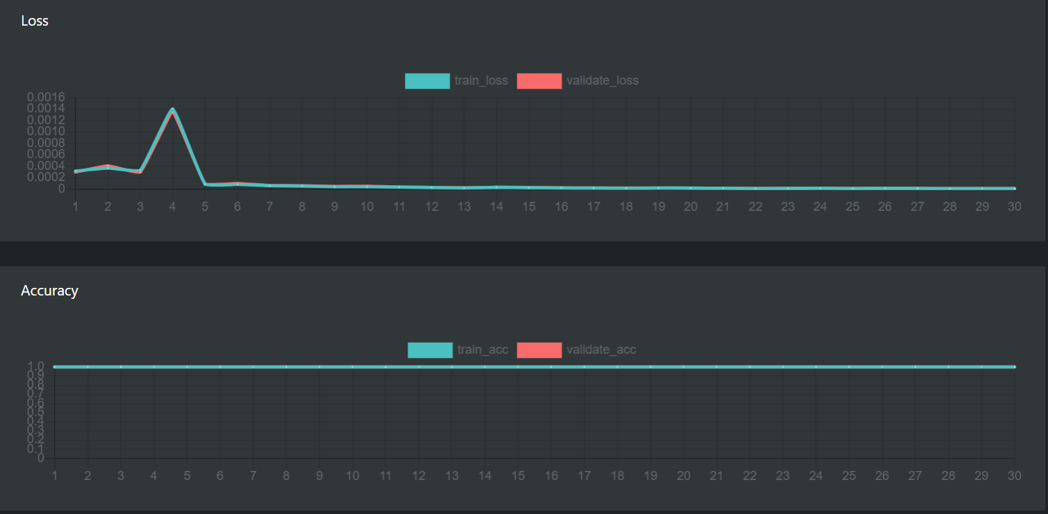
Observing the training progress, the accuracy of multiple training sessions is 100 percent, indicating that the model for detecting whether the plug is properly inserted is more stable.
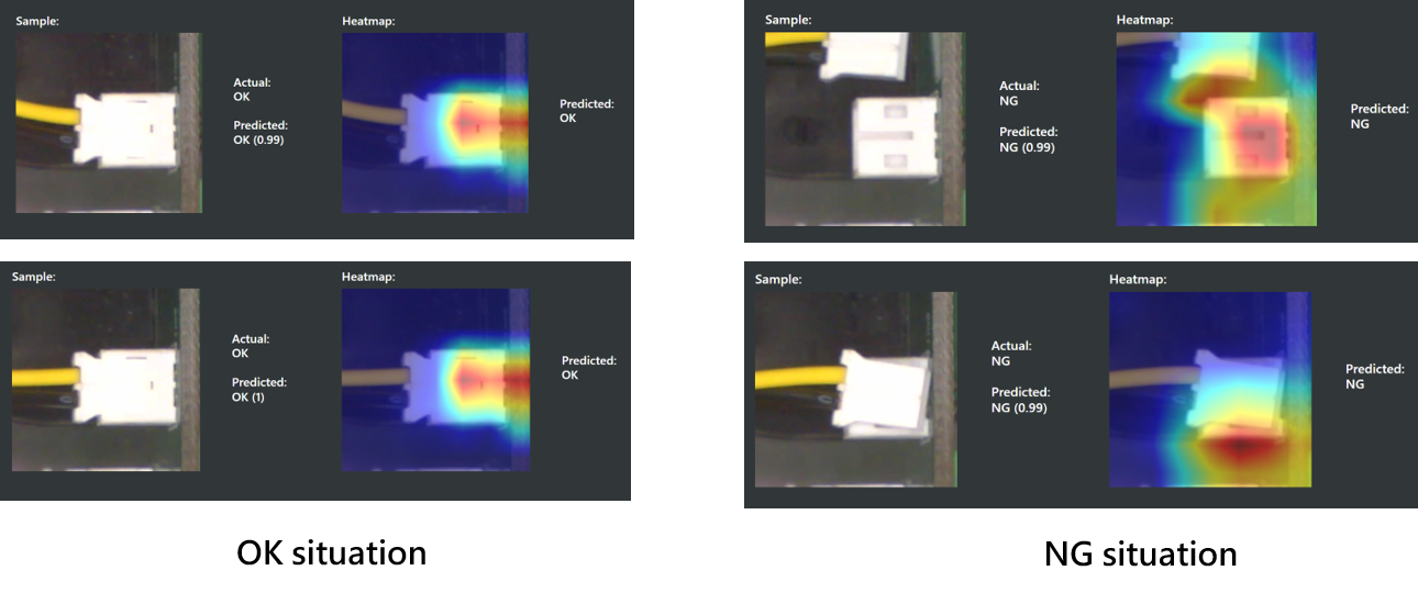
By using the heatmap, we found that the features learned by AI focused on the small black hole at the top. If it is not properly inserted, the black hole at the top will be particularly obvious and will be judged as NG. The result is as we expected. The heatmap of the NG situation also pays attention to whether the black hole at the top is too obvious, or whether the plug is completely detached. After importing the model into the robot, it can also run smoothly in various situation.
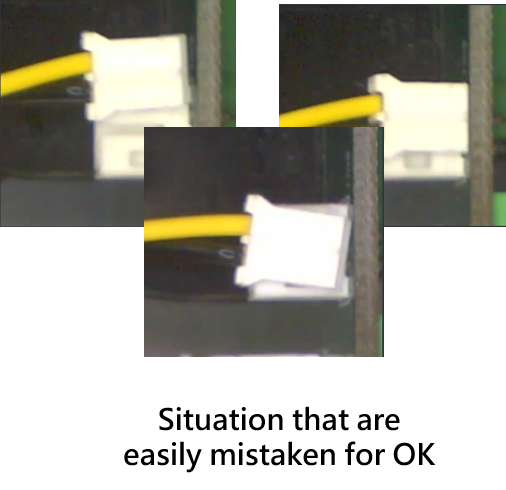
Then we switched to another robot and environment for testing, and found that the situation of complete detachment was easily judged as OK. We guessed that the change of light source caused the wiring to be unclear, and mistakenly judged the situatin of the wire head lying flat on the top of socket. So in this environment, we added about 20 more NG situations, and also added about 20 more OK situations to adapt to the environmental changes.
TM AI+ – whether there is a screw in the screw hole_top shot of the IPC #
Observing the training progress, the accuracy of the training session is mostly 100 percent, indicating that the model for detecting whether there are screws in the screw holes under the condition of shooting the IPC from above is stable.
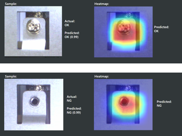
By using the heatmap, we can see that AI can learn the feature of whether there are screws on the holes under any light source. After importing the model into the robot, the test is also very stable.
Then we switched to another robot and environment for testing, and it can also stably distinguish, without changing the model.
TM AI+ – whether there is a screw in the screw hole_side shot of the IPC #
Observing the training progress, the accuracy of the training sessions is also mostly 100 percent, indicating that the model for detecting whether there are screws in the screw holes under the condition of shooting the IPC from the side is also stable.
- Observing the heatmap, the features that AI focuses on are indeed on whether there are screws in the screw holes. But when importing the model into the robot for testing, some angles of the screw holes are easily affected by the ROI selection and recognized incorrectly, indicating that this model is not stable enough and the data is not enough.
- It is recommended to consider the image of screws taken from above and train them together to obtain a relatively stable model. You can also combine the previous data on screw locking to train a more robust model. In this way, this model can be applied to most of the screw holes on this IPC.
- Considering the model trained with more data, it can also stably judge whether there are screws in the screw holes after switching the robot and environment.
TM AI+ – whether the cable is connected correctly #
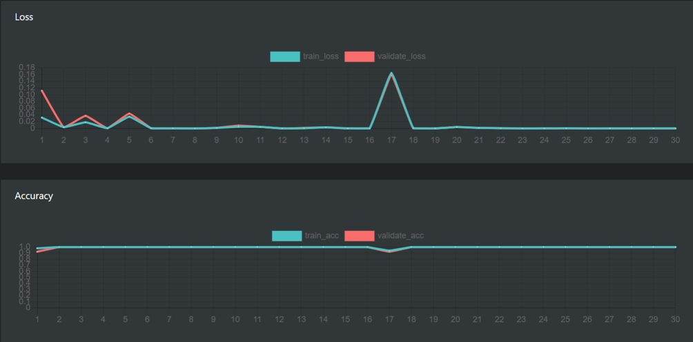
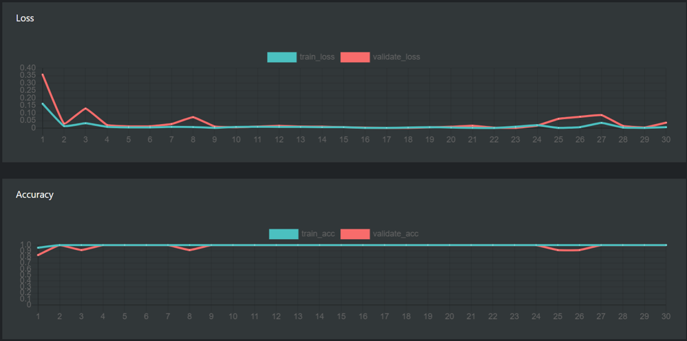
Using the above-mentioned image acquisition method for the first training, the training progress is less stable than the previous situations.
Observing the heatmap, we cannot determine whether the situations of OK overlapping and CROSS have been learned by AI. We need to import the robot for actual testing.
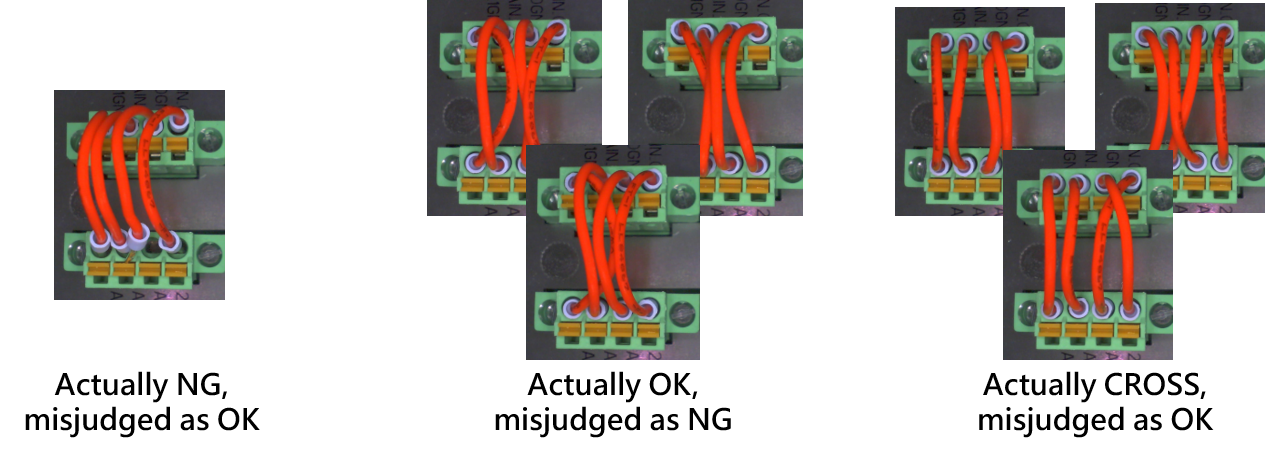
1.After importing the robot testing, we can find that the two crossed lines under CROSS are easy to judge as OK, while the three and four crossed lines have no problem.
2.And under the NG situation, the lines that are not inserted side by side are also easy to be judge as NG.
3.Under the OK situation, if there is overlapping, it is also easy to judge as CROSS.
After collecting about 20 images of the misjudged situations and retraining, the problem still could not be improved, and even failed to converge to a more correct result.
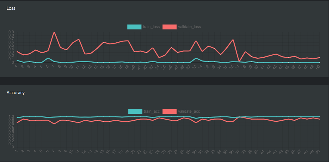
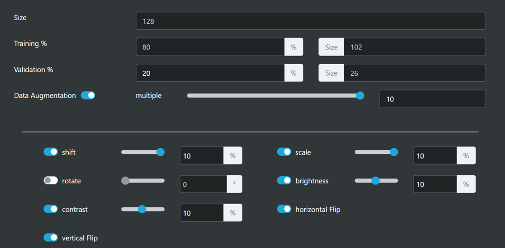
So we changed the model selection from Regular to Ultra for training, performed data augmentation, and some minor parameter adjustments, to make it consider more variations.
1.Epochs increased from 30 to 100, giving it a chance to find a convergent result.
2.Batch Size is set smaller, so that it will not see too many possibilities at the same time, and cause it to fail to converge.
3.Learning Rate is slightly adjusted lower, so that it has more chance to reach a lower Loss.
After the adjustment, the training progress has found a lower Loss, and some 100 percent Accuracy has appeared, but it is still not certain that the trained model is reasonable.
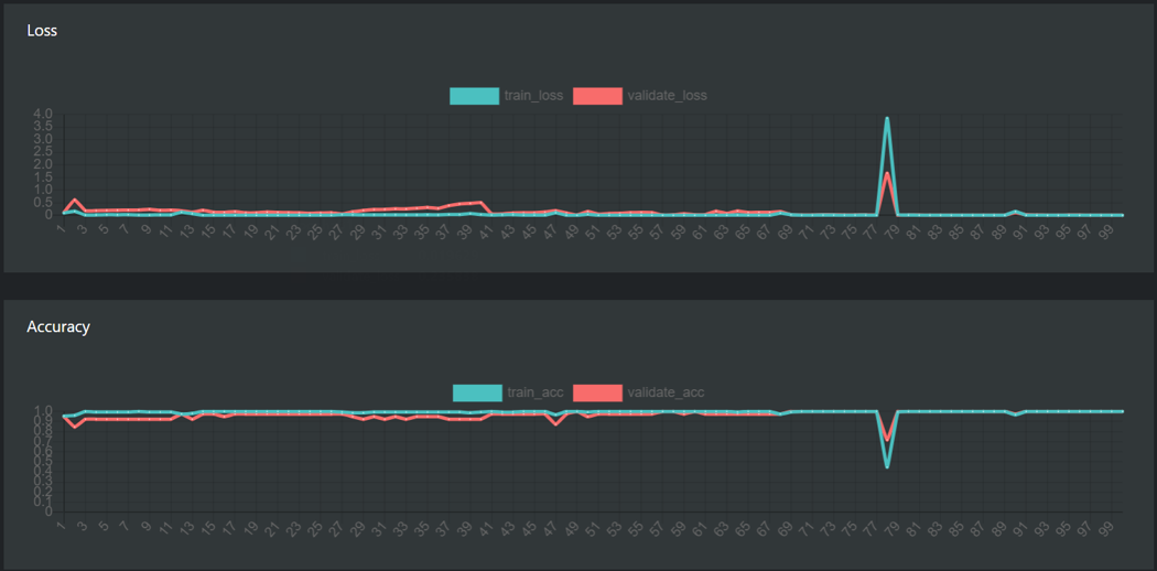
Then import this model into the robot test, which improved the following issues
- NG situations will no longer be misjudged as OK
- CROSS situations will no longer be misjudged as OK
In OK situations, if there are overlapping issue, they still cannot be recognized.
It is recommended to treat OK situations with overlapping issues as CROSS, they still need to be adjusted by inspection personnel.
Therefore, the problem is reclassified as follows:
- One-to-one correspondence, the wires need to be clear, regarded as OK.
- The wire head is inserted correctly, but it is crossed or there are nodes, regarded as CROSS.
- The wire head is not inserted correctly, regarded as NG
After readjusting the classification, perform model training and observe the heatmap, and find that AI can correctly learn the nodes caused by the crossing of wires and the holes exposed by not inserting correctly.
Finally, import the robot and change the environment for testing, and it can run stably.
Tip #
- When collecting images, you can first collect about 30 images for training, and then import them into the arm test. If there are misjudgment situations, you can collect another 20 images of the error situations for testing.
- If the model training result is not satisfactory, you can use the Ultra model for training, and adjust the augmentation appropriately, considering that the object may have symmetry or scaling situations.
- If the model training is unstable, you can increase the Epoch to 50 to 100, so that it has a chance to find a convergent result. Learning can be lowered to about 0.00008, so that it has a chance to find a lower Loss.

