TMflow Software version: All versions.
TM Robot Hardware version: All versions.
Other Specific Requirements: External Camera and Lens
Note :
- Older or latest software versions may have different results
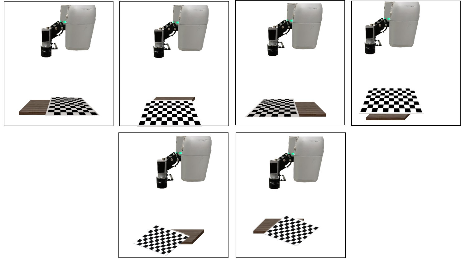
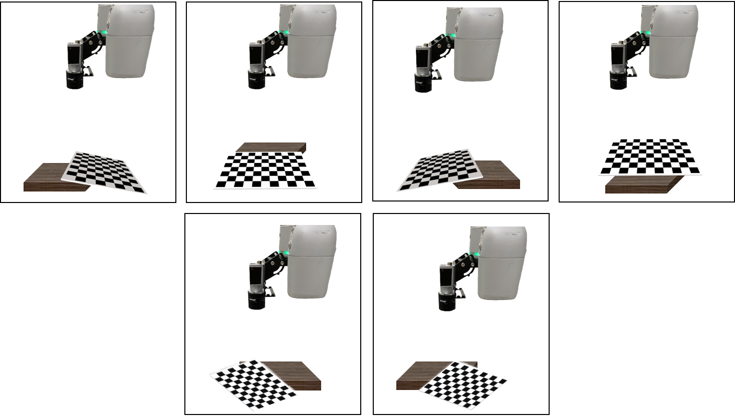
- While placing the TM Calibration Plate with an inclined angle, please ensure that the plate is not bent or distorted, especially for larger plates.
Purpose #
While using an external camera, whether in the EIH or ETH setting, it is essential to calibrate the intrinsic parameters of the camera. After determining the working distance between the camera and the object to be inspected (target), adjustment to the lens aperture and focus is required since it helps enhance imaging precision and quality, and minimize image distortion and errors.
How to Set External Camera? #
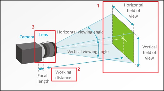
- Determine the observation range for the target and camera’s FOV. Note that lenses with different focal lengths correspond to different FOVs. For detail concepts, please refer to Section 5 in How to choose a camera, lens, and light source.
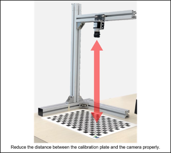
- Adjust camera position to the appropriate working distance.
- Select a lens, which has adjustable aperture size and focus, with an appropriate focal length. During the adjustment procedure, try to minimize the aperture size; a smaller aperture helps correct intrinsic parameters, resulting in a larger depth of field. This is particularly effective for capturing clear images of titled TM Calibration Plates. If there is insufficient brightness in the environment, try to adjust exposure time or external light sources. After tuning the aperture and focus, ensure that the screws of the camera are securely tightened to prevent any unexpected change in the intrinsic parameters during the calibration process or robot movement.
Intrinsic Parameter Calibration Process #
Whether in the EIH or ETH setting, calibration of intrinsic parameters is required while using an external camera. If the aperture and focal length of the camera are changed, it is necessary to recalibrate the intrinsic parameters.
- To start the intrinsic parameter calibration process, press the corresponding buttons to enter the calibration procedure, and collect 15 images.
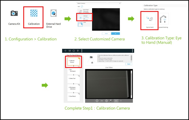

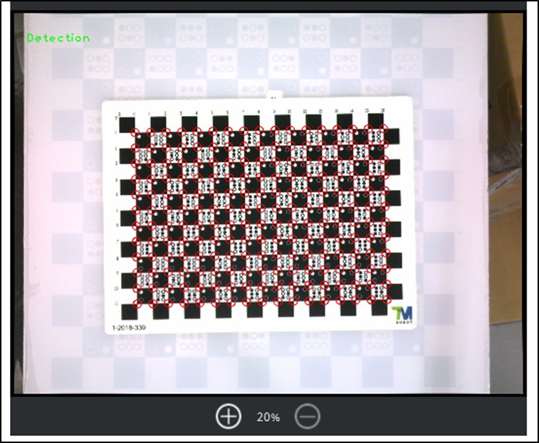
- An appropriate calibration FOV must allow the camera to at least recognize an area of 5×5 squares on the TM Calibration Plate, and the size of the plate should be larger than half of the FOV.
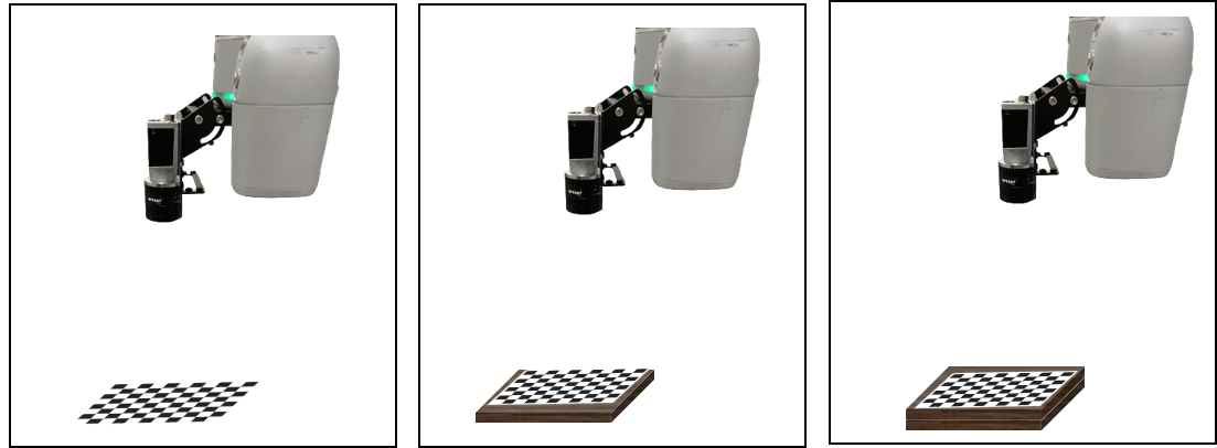
Below are some recommended poses to place the TM Calibration Plate during the calibration procedure. There are 15 poses in total.
- Finally, raise the calibration board to three different heights.

