TMflow Software version: TMflow 2.20 or above versions
TM Robot Hardware version: HW3.2 or above versions
Note : Older or Latest software versions may have different results.
Purpose #
- Flying trigger feature allows TM Robot to move and capture images without stopping, improving the cycle time of vision inspection.
- Flying trigger feature has integrates motion control, digital signal output and image capture. Users only need to set the vision capture point, digital IO port and vision job, and the settings can be easily completed.
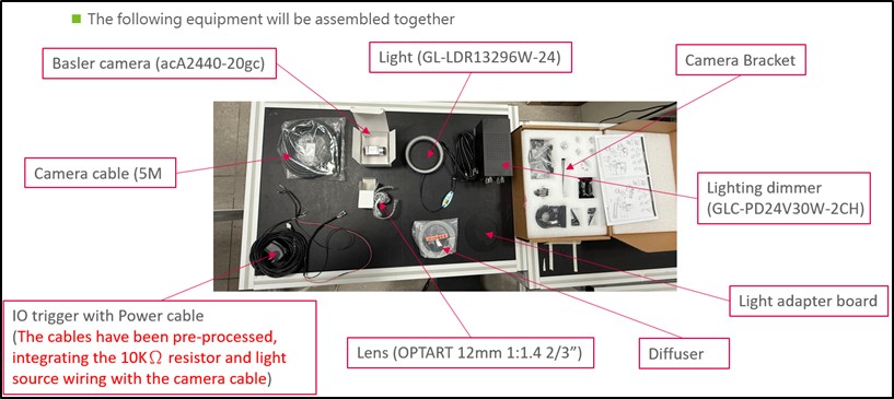
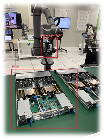
- In this document, we take server inspection as example, environment setting are as follow.
Camera Parameter Setting #
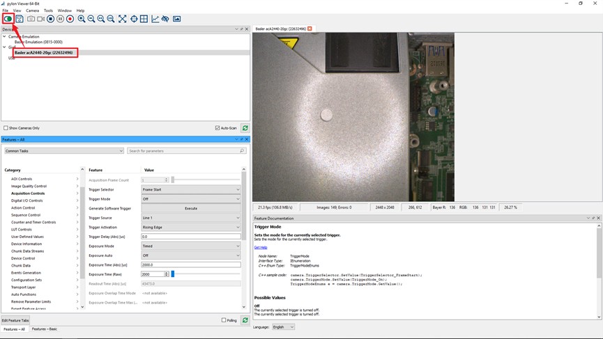
Connect the camera to a personal computer and launch pylon. For installation and usage instructions, please refer to the following Basler website (pylon Software for Image Capture >> At a Glance | Basler AG (baslerweb.com)).
Next, adjust the light source synchronization settings. Click on Digital I/O Controls, set Line Selector to Line 2, Line Mode to Output, and Line Source to Exposure Active.
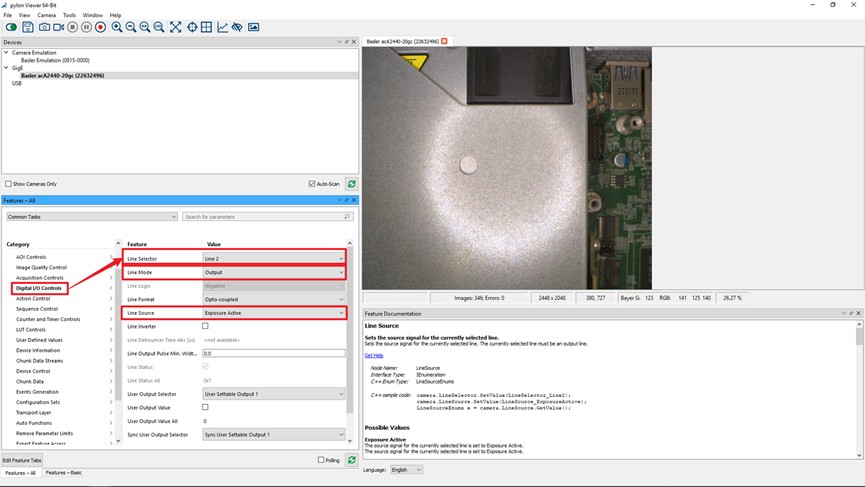
Finally, save all parameters to User Set 1. This configuration will be stored on the camera.

Finally, save all parameters to User Set 1. This configuration will be stored on the camera.

Wire Connection #
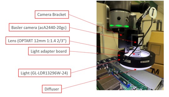
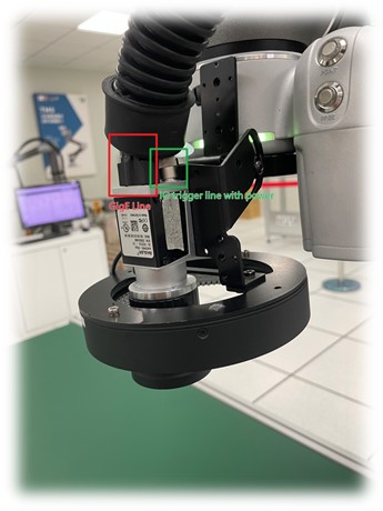
After configuring the camera parameters, mount the camera onto the robot and connect the GigE and trigger cables.
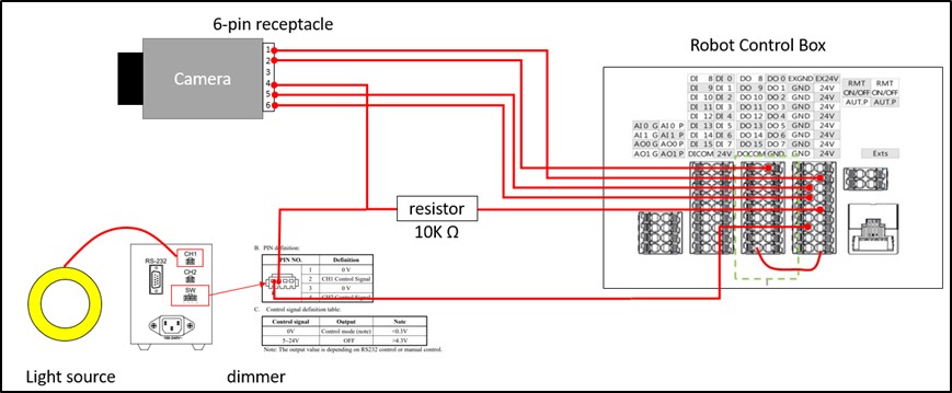
The circuit diagram and actual wiring method are as follows.
TMflow Process Operation #
Create a project and perform positioning based on the prominent features identified on the server. Subsequent points will be moved and inspected according to this vision base.
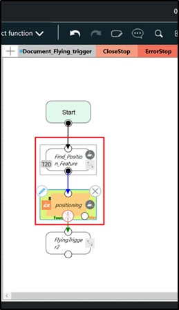
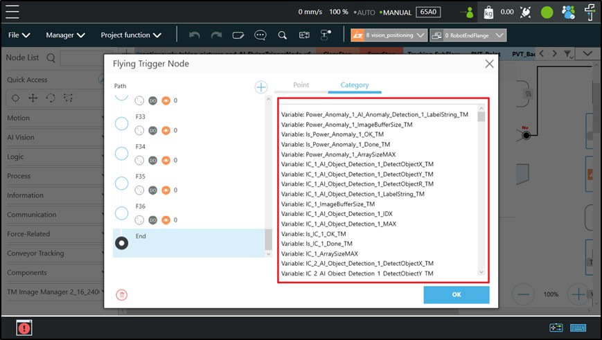
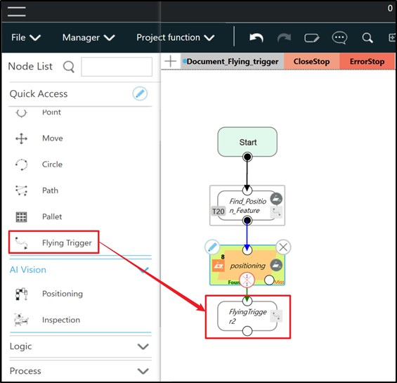
Create a Flying Trigger node and open this node.
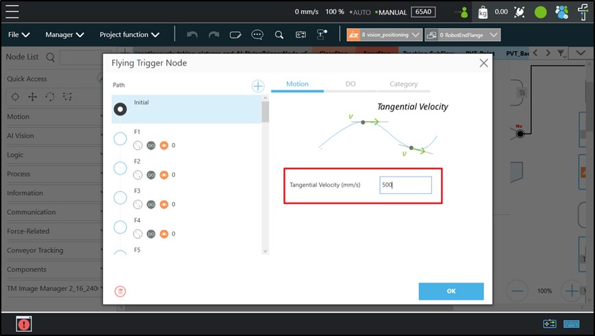
Set the Motion velocity in the initial configuration
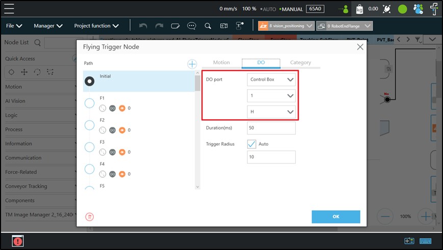
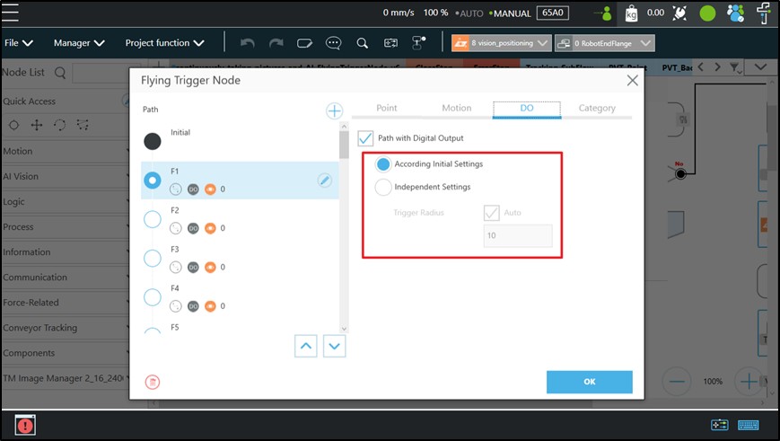
Configure the DO(Digital Output) that triggers the camera capture. Adjust the DO position based on the location where PIN 2 is connected during wiring. In this setup, DO 0 is used to trigger the camera capture.
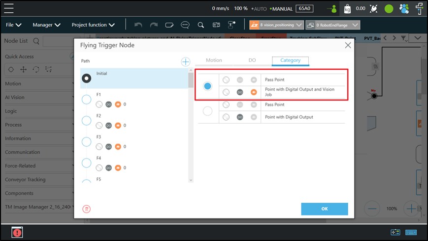
In the Category selection, choose Point with Digital Output and Vision Job.
Move the robot to the inspection position and add a new point.
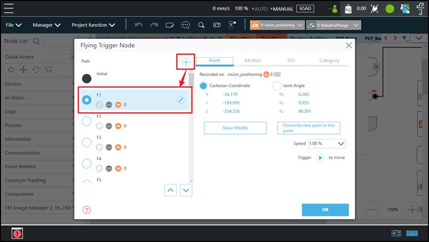
Both Motion and DO settings can be applied from the initial configuration, or you can individually adjust the velocity and DO settings according to the specific needs of each position.

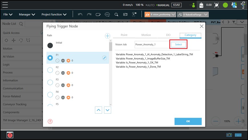
In the Category section, click select to edit the vision job.
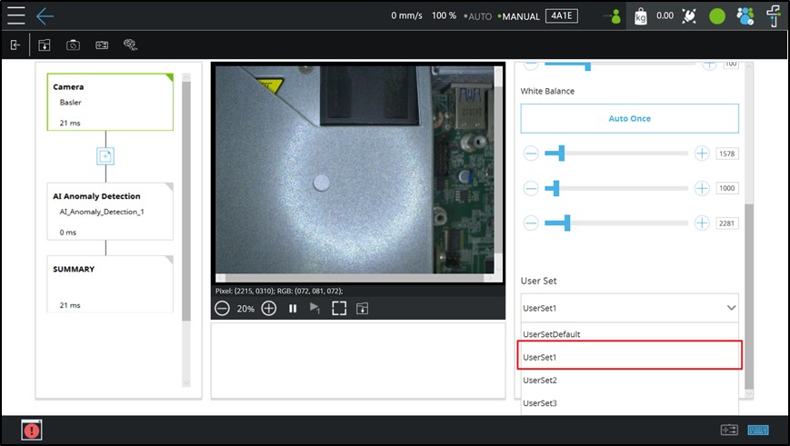
Within the vision job, select UserSet1 in the camera setting.
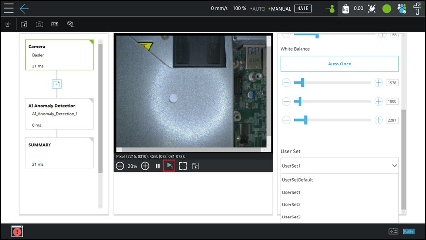
Clicking the Play one button will set DO 0 to High and trigger the camera to capture an image.
Complete the subsequent inspection process and save the vision job.
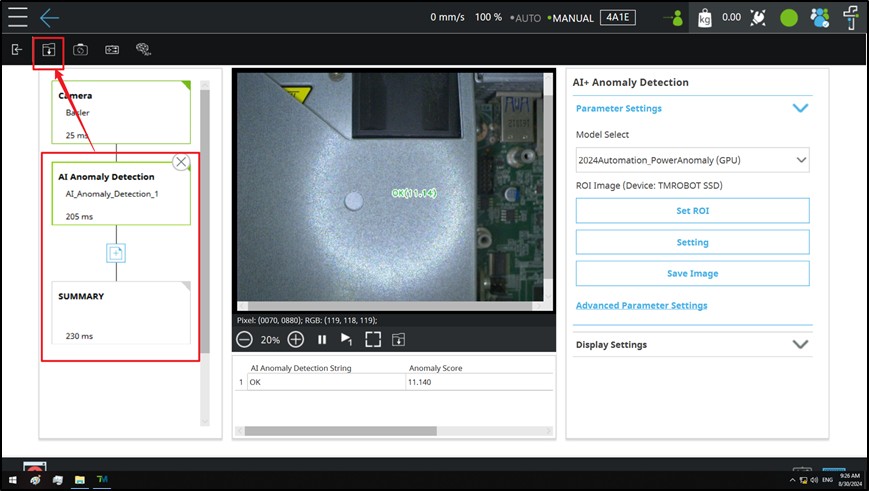
Similarly, complete all points and their corresponding inspection tasks.
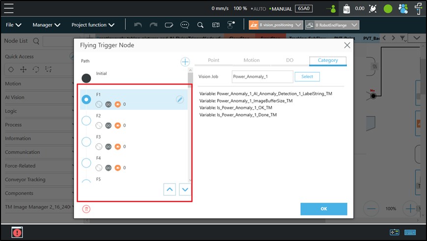
You can view all the vision job variables in the End section.