Examples are valid for:
TMflow Software version: 1.76.6300 or above.
TM Robot Hardware version: All versions.
Note that older or newer software versions may have different results.
Operation Space -Overview #
TMflow provides two spatial characteristics of plane and cube for operation space environment construction. When the robot crosses different operation spaces while running, the robot will switch between stop, Reduced Mode, and full speed mode. When calculating the position of the robot and its related actions in Operation Spaces, the TCP is used as the reference point. In other words, the position of the TCP decides the actions in Operation Spaces of the robot. When working in the Reduced Mode, all the safety settings, including TCP speed, TCP force, joint torque etc. follows the settings in Human – Machine Safety Settings. When working in the full speed mode, all the safety settings includes TCP speed, TCP force, joint torque and etc. follows the settings in Performance Safety Settings. However, pay attention that this function is not a safety function defined by TM Robot. This function is only suitable for dividing operation space, assisting users in understanding the spatial concept during teaching and programming, or letting the robot decelerate in advance to allow smoother deceleration before the robot moves through a safety sensor installed in the space.
Regarding switching and triggering of Human – Machine Safety Settings, use the User Connected External Safeguard Port for Human – Machine Safety Settings of this product. Add appropriate safety devices such as appropriate installation and configuration of safety sensors connected to the safety protection port with dual channel connections.
Operation Space Setting Page #
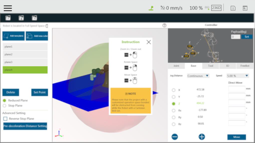
Click Operation Space in the Robot Setting Page to access the Operation Space Setting Page. As shown in the figure below, the left side of this page provides space setting, the middle is the virtual robot interface, and the right side is the controller interface.
- Add new plane: Add plane
- Add new cube: Add cube
- Delete: Delete the selected characteristics
- Set Point: Reset characteristics
- Reduced Plane: Switch to reduced plane
- Stop Plane: Switch to stop plane
- Reverse Stop Plane: Check to reverse stop plane
- Pre-deceleration Distance Setting: Pre-deceleration distance
Add / Modify Page #
Plane Page #
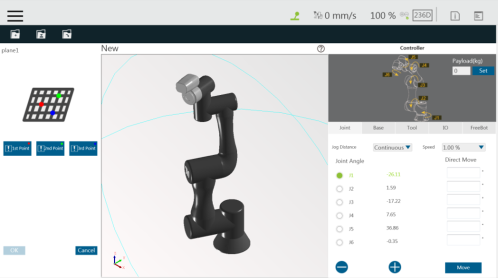
The Add/Modify Plane Page can be accessed by clicking the button to add a new plane or clicking button to reset characteristics after selecting the plane characteristics.
On this page, users can build a plane by setting three points. The setting order of the three points can be random, and the robot virtual interface will display the corresponding color ball. When the three points are set, a dark blue virtual plane will appear. At this time, clicking OK will lead to building the plane.
It is necessary to pay attention that once the phenomenon of common point or collinearity occurs, it is not possible to build the virtual plane. The button function list is shown below.
Cube Page #
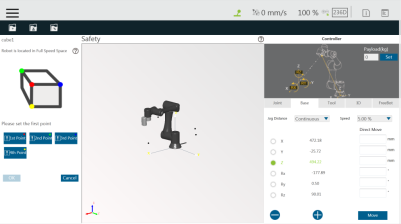
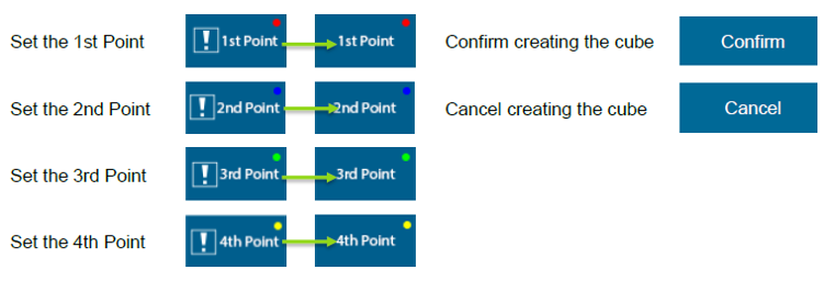
The Add/Modify Cube Page can be accessed by clicking the button to add cube or clicking the button to reset characteristics after selecting the cube characteristics. On this page, users can build a cube with the four points setting by TCP. The setting order of the four points can be random but in accordance with relative relationships as illustrated on the screen. The robot virtual interface will display the corresponding color ball. When the four points are set, a dark blue virtual cube will appear. At this time, clicking the OK button will lead to building the cube. It is necessary to pay attention that once the phenomenon of common point or collinearity occurs, it is not possible to build the cube. The button function list is shown below.
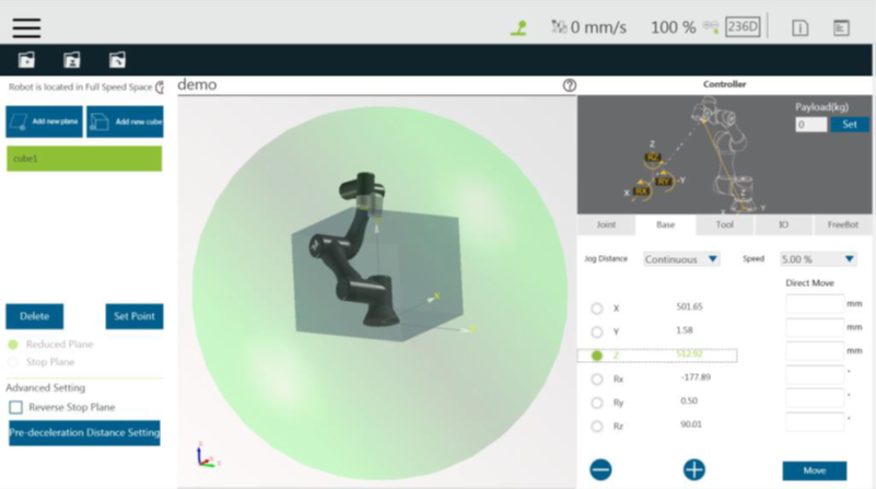
Once completed building the operation space, users can identify objects in the 3D screen as shown below. The whole sphere is the maximum movable range of the robot, the reduced space is in green, the full speed space is in red, and the stop space is the space removed from the robot’s movable
Operation Space Setting Page in the Project Editing Page #
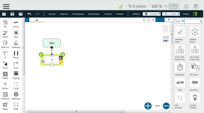
After building the plane, users can go to the Project Editing Page and click Operation Space in the project function menu for Operation Space Setting.
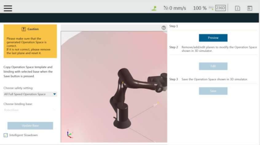
The Intelligent Slowdown function in the lower left of the figure above provides the ability for the robot to automatically pre-decelerate in the schedule of the project node. If this function is checked, when the project is running, the system will calculate whether the robot’s next node position crosses the space. If the space is crossed, then the robot will start deceleration at the current node.
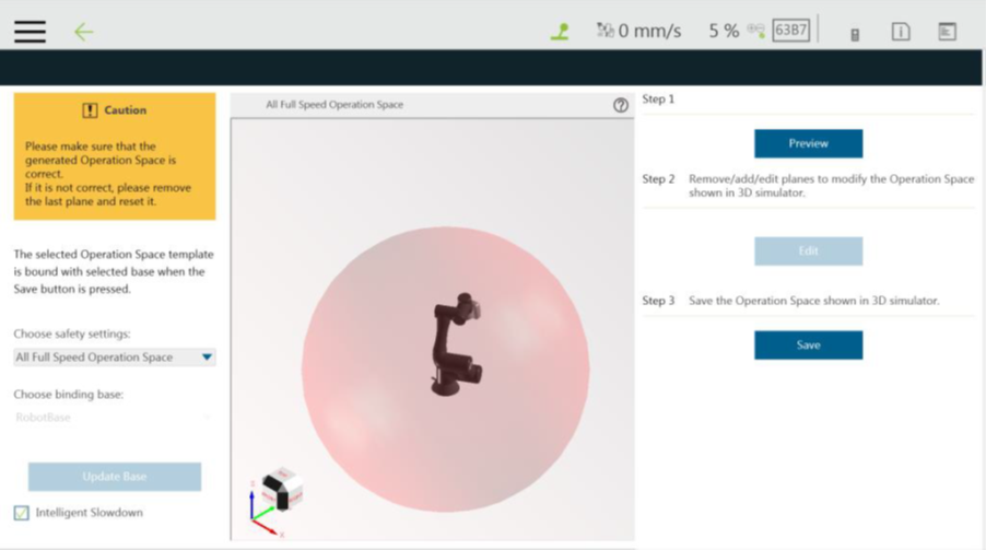
In the Project Function Menu of Project Editing Page, click Operation Space > Preview to display the 3D simulator with the selected operation space in Select Operation Space Setting and the base in Choose binding base. To modify the operation space, click Edit. Users are responsible for checking the correctness of the displayed operation space and maintaining its safety before saving it. If not correct, click Edit to remove the last plane and set again. The system will save the operation space displayed in the 3D simulator after clicking Save. Binding Base is a convenient function for users to record the definition of the operations space in the ambient bases, but please note that binding is a one-time action. If the Base is updated in other interfaces after binding, it is necessary to go back to this page to bind again.
After clicking the Preview button, if the set page needs to be modified, click the Edit button below to modify the screen.
- Preview: Display the generated operation space on the 3D simulator.
- Edit: Delete, add, or edit planes to modify the operation space displayed in the 3D simulator.
- Save: Save the Operation Space displayed in the 3D Simulator.

