Examples are valid for:
TMflow Software version: 2.22.2400 or later.
TM Robot Hardware version: HW5.02 or later only
Other specific requirements: Refer to Preparation section below.
Note1: that older or newer software versions may have different results.
Note2: TM does not provide the hardware of AUX. System integrators should prepare their own hardware.
Note3: the AUX functions work on real a cobot and positioner, not in the TMflow simulator.
Goal #
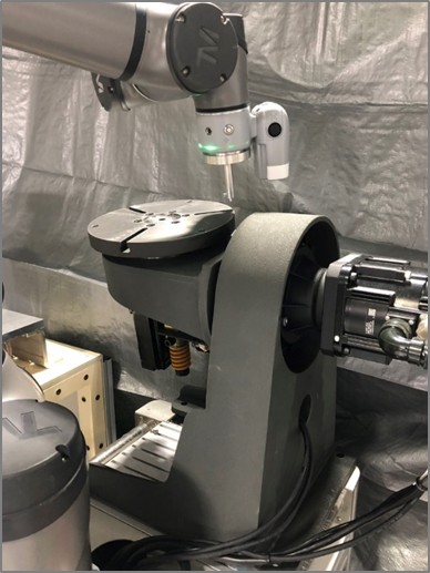
This tutorial is designed for system integrators to guide them in integrating their own external positioner (1-axis or 2-axis, referred to as AUX in this article) with a TM cobot for synchronized motion control. An external positioner is particularly valuable in applications such as welding or dispensing.
Terms #
|
Name |
Description |
| AUX | Auxiliary axis, known as a positioner |
| Positioner Node/Toolbar | The UI done with TMcraft API |
| Base | Activated coordinate system for reference |
| TCP |
Activated tool center point |
Changelog #
| Data | Description |
| March 26 2025 | 1st release |
| July 24 2025 | Add safety notice |
Preparation #
Before implementation, there are recommended items to study and prepare:
- TM robot with TMflow2.22.2400(or later) and a cobot with HW5.02
- Download and unzip Positioner Node/Toolbar Package to a USB stick Download Here

- The hardware of a positioner (only supports Yaskawa servo motors – Sigma X EtherCAT)
- A laptop with the servo configuration tool
- Wiring for the servo motor system
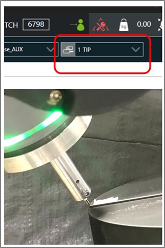
- Set correct TCP data with the torch and base
Related materials:
- TMflow Software Manual – for basic operation of TM Cobot.
- TMscript for Auxiliary Axis – TMscript commands for the auxiliary motion. Download Here

- Source Code of TMcraft Package – the source codes could be found here in case you want to modify the TMcraft Package for AUX. Visual studio 2022 and C# are required. Download Here

- TMcraft API – This is a beta version of TMcraft API especially for AUX. Refer to the TMcraft.dll in the Source Code for more information.
Safety Requirement #
-
Since the external axis cannot meet collaborative safety standards, developers must evaluate the arm’s operation mode in this case, which may require equipment such as safety fences.
Behaviors of AUX #
- The AUX and the cobot are regarded as a single entity. For example, actions such as emergency stop, pause, start, and stop will also apply to the AUX.
- When using synchronized motion, the cobot adjusts the TCP speed to be relative to the AUX plate. For example, if an absolute speed of 10 mm/s is selected, the TCP will move at 10 mm/s relative to the AUX plate while the AUX is in motion.
- The AUX can be jogged separately without moving the cobot.
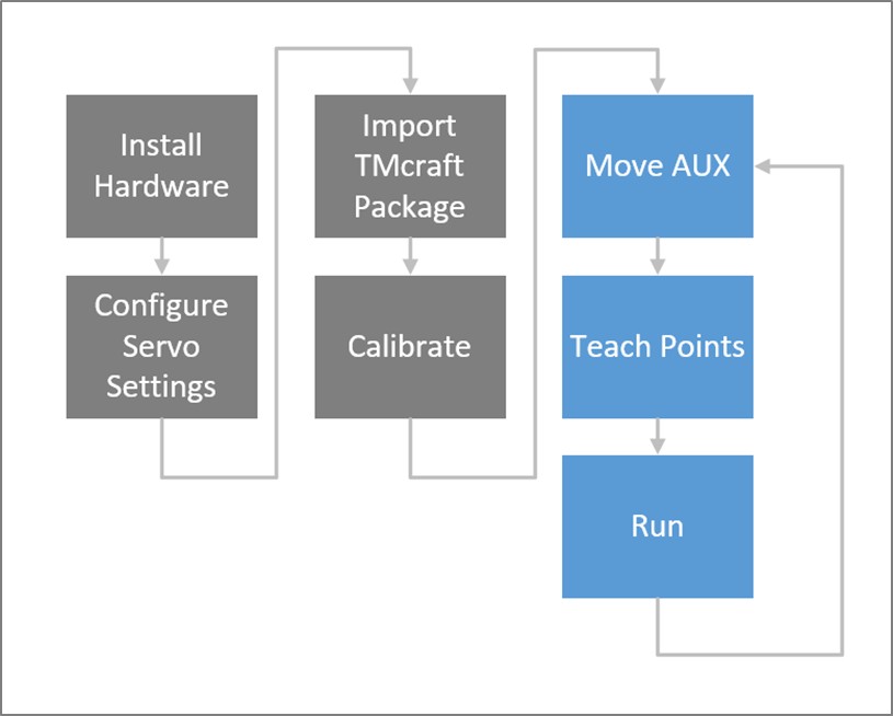
Work Flow for Operating AUX #
Before using AUX, there are some steps should be completed. Detailed information will be described step by step.
Install Hardware #
An additional hardware is required:
- 1-axis or 2-axis AUX with Yaskawa servo motors (sigma-X series)
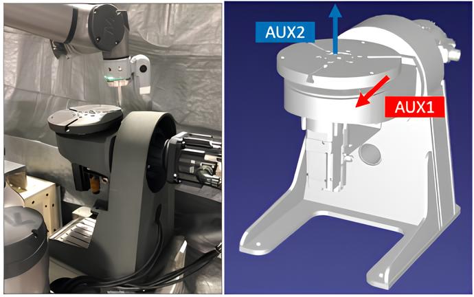
- This this article, we use:
- Tilt axis driver: SGDXS-7R6AA0A
- Tilt axis motor: SGMXG-09AUA6CC2
- Rotary axis driver: SGDXS-2R8AA0A
- Rotary axis motor: SGMXJ-04AUA6EC2
- Wiring example for the servos:
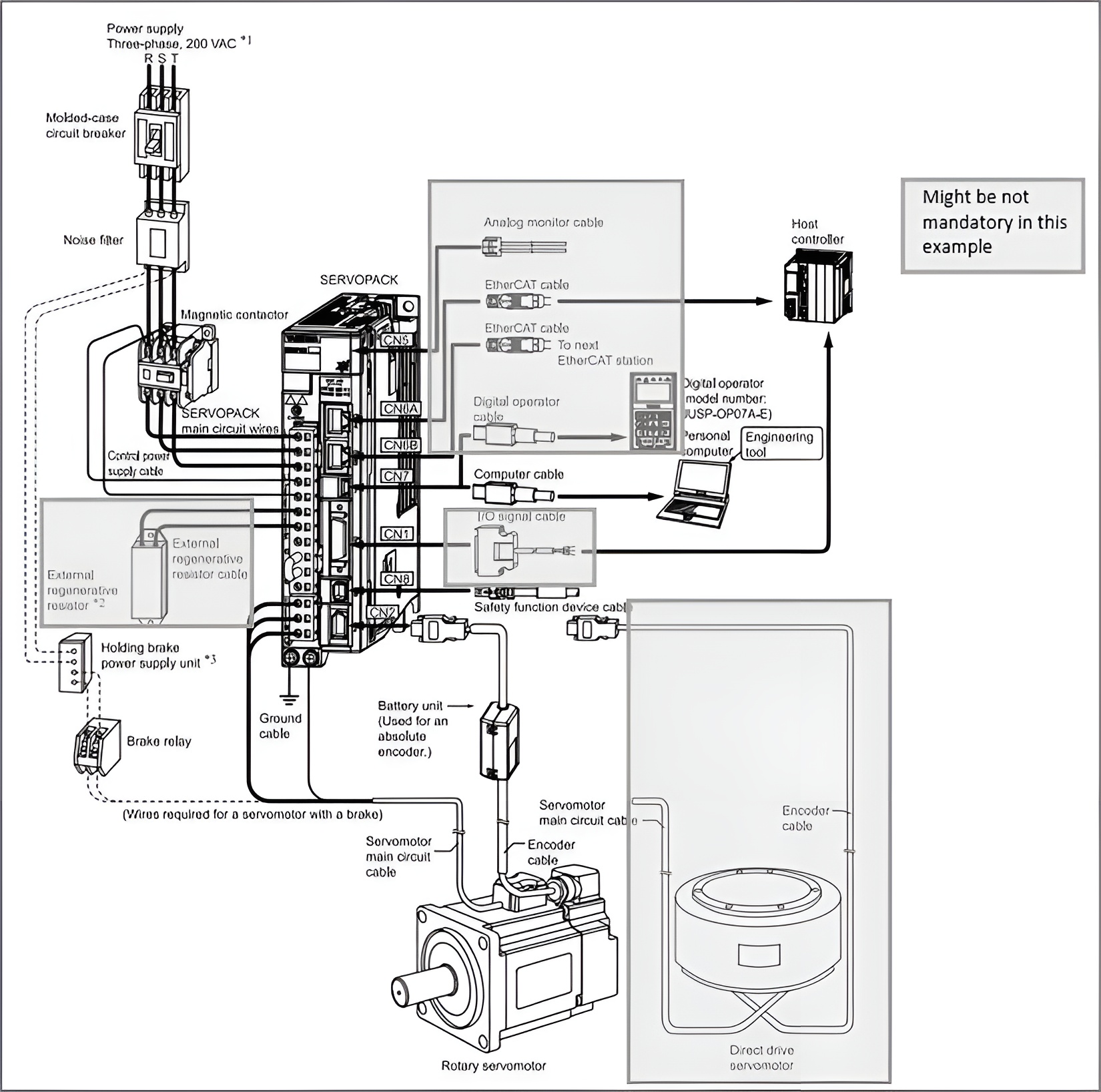
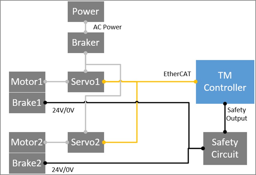
For more information, please refer to the manual from Yaskawa.
Configure Servo Settings #
- Install the configuration tool (Sigma Win+) from Yaskawa on a laptop.
- Connect an USB cable to the drivers, then perform servo turning with the tool. For more information, please refer to the manual from Yaskawa.
- Perform zero calibration.
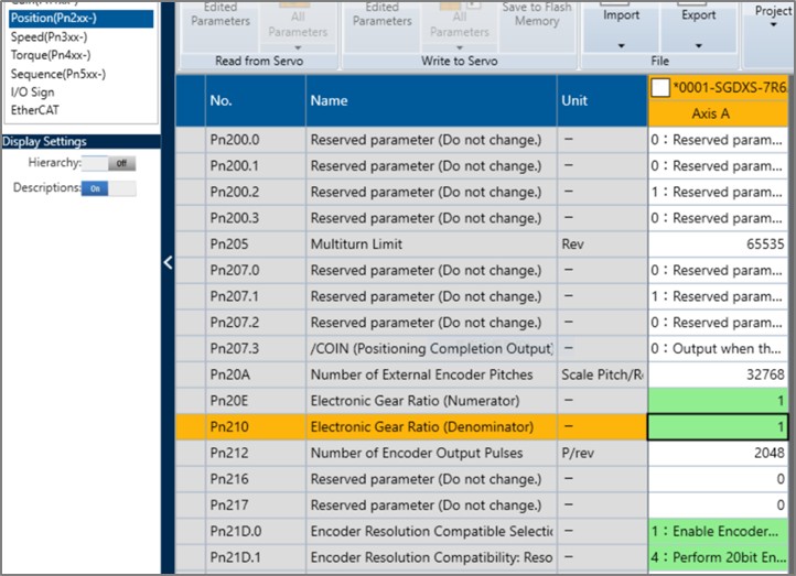
- Configure parameters in the tool, then save to the drivers and reboot.
Parameter Value Pn000.0 Please set the correct direction (0/1) based on the right-hand-rule. Pn20E/Pn210/Pn21D.0 1 Pn21D.1 4 Pn50A.3/Pn50B.0 8 PnB48 -53687090912 PnB4A 53687090911 PnBBE -2147483648 PnBC0 2147483647 PnC70 603F0010 H PnCA4 9 PnCB6 1600 H PnCBC 1A00 H
Import TMcraft Package #
- [On the laptop] Prepare an USB stick named TMROBOT
- Unzip TMcraft Package in Preparation, and copy the folder TM_Export to the root of USB stick.
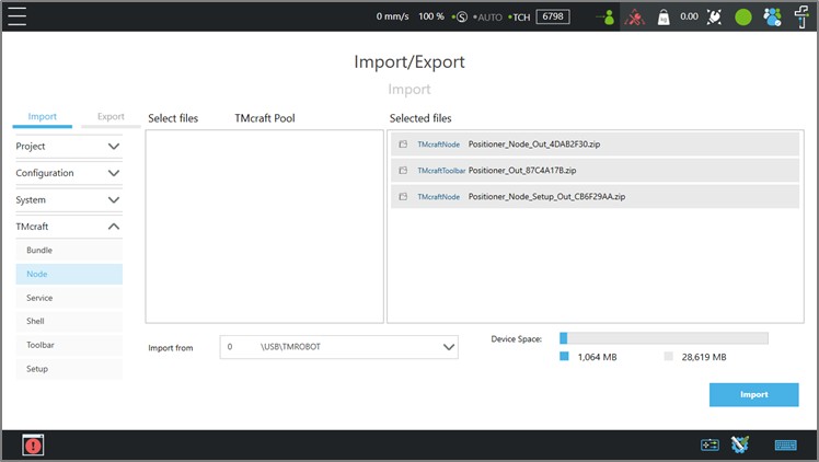
- [On the cobot] On TMflow2, navigate to Menu/System/Import, and import the files from USB stick. There should be 3 files as below:
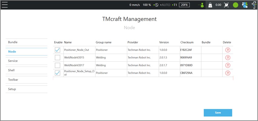
- Navigate to Menu/Configuration/TMcraft Management, enable two nodes and one toolbar.
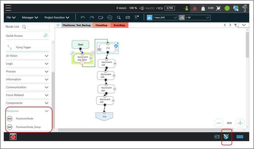
- Once the steps are done, there should be icons as below in a TMflow project :
Calibrate for AUX #
- [On the servo drivers] Turn on the drivers and ensure that there are no error codes on their monitors.
- [On the cobot] Calibrate the TCP first. Ensure that the correct TCP is activated.
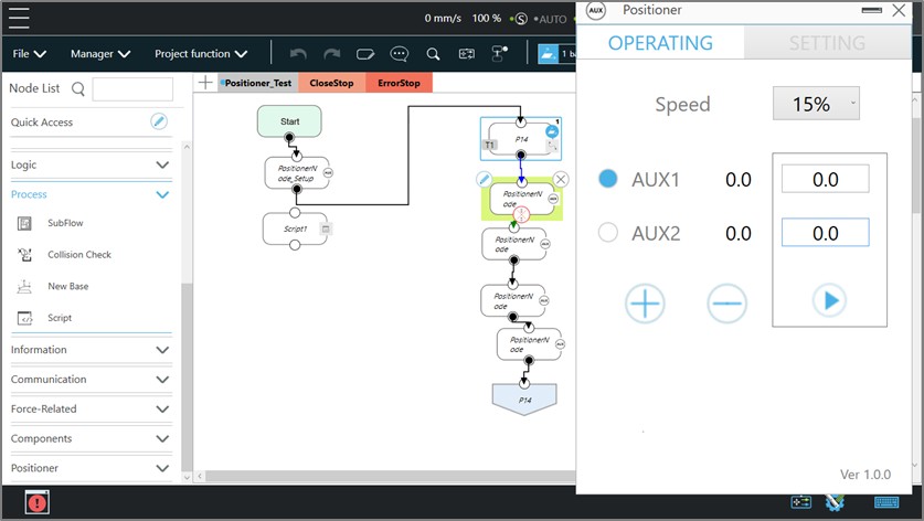
- Navigate to the Positioner toolbar. Jog [AUX1, AUX2] to [0, 0] position. Hold PLAY icon to move AUX to target position.
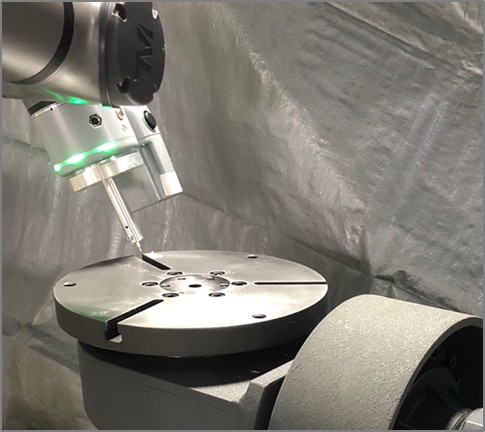
- Choose an appropriate calibration point on the edge of the rotary plate (e.g., AUX2). Consider the following hints:
- Find a sharp edge that is easier to align visually during subsequent calibration procedures.
- For a 2-axis system, any position on the edge is guaranteed to work.
- For a 1-axis system, this point must be on the positive X-axis.
- Mark the corner to facilitate later alignment.
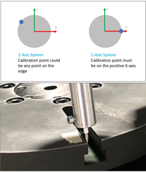
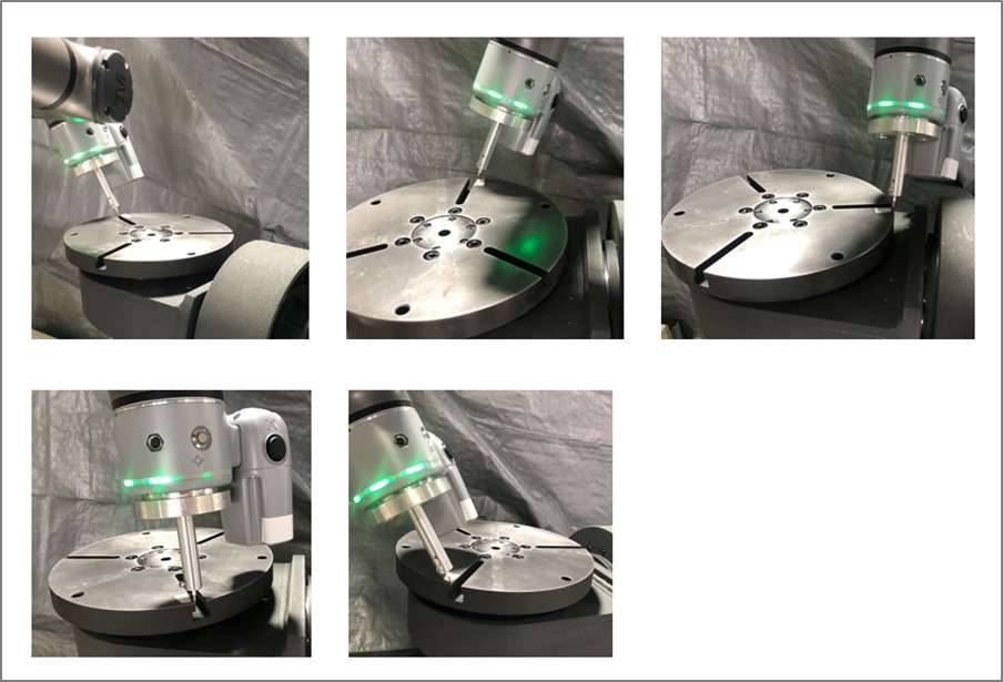
Find a Propriate Calibration Point on AUX
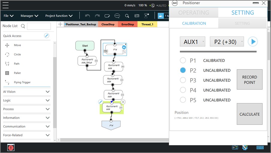
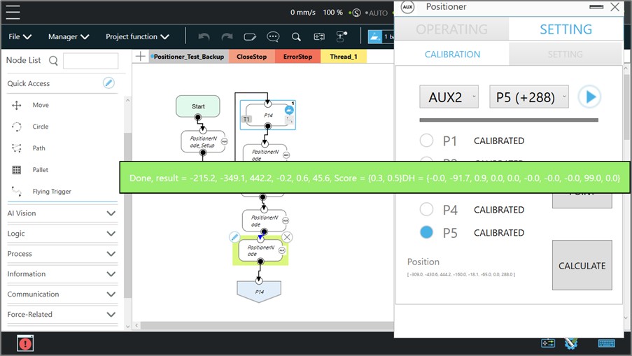
- On the Positioner toolbar, navigate to SETTING/CALIBRATION. Select AUX1 and P1(0°), then hold the PLAY icon to move to P1 point.
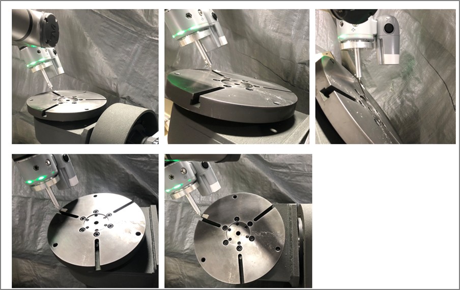
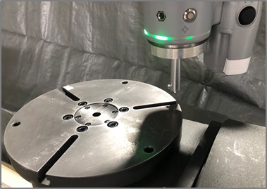
- Manually guide the TCP to lightly touch the calibration point. The orientation (angle) of the TCP does not matter. Hit Record Point. You will now see that P1 is calibrated.
- Move the TCP away, then follow the same procedures to finish AUX1.P1 to AUX1.P5.
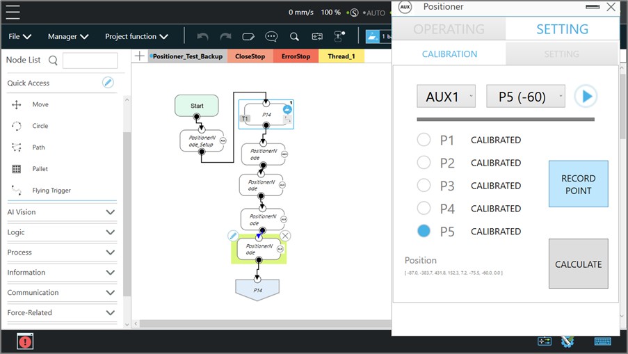
- Move AUX1 to 0.
- Select AUX2 and P1(0°), then hold the PLAY icon to move to P1 point.
- Follow the same procedures to finish AUX2.P1 to AUX2.P5.
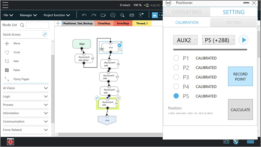
- There are predefined positions from P1 to P5. You can move to different positions, but ensure that these points cover as much of the working range as possible (e.g., 0° to 360° for AUX2).
- If a 1-axis AUX is attached, calibrating the AUX1 points is sufficient. Skip AUX2.
- Once all points are calibrated, press CALCULATE and review the results. A score between 0.3 and 0.5 indicates the accuracy of the calibrated results for AUX1 and AUX2. A score less than 0.5 is recommended, or recalibration will be necessary.
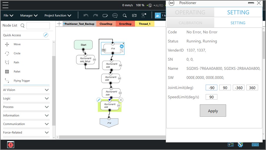
- Navigate to SETTING/SETTING to check the status of AUX and modify the settings if desired. Then hit Apply for any changes. These settings could be modified at any time.
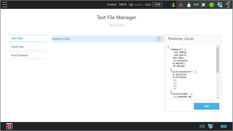
- Once the calibration and settings are complete, a text file will be created at TMflow/Text File Manager/Positioner_Cal.txt for later usage. It contains the following information:
- Base data of the AUX (the position of the rotary plate’s center relative to the robot base).
- DH parameters(describing the physical relationship between AUX1 and AUX2).
- The rotational speed limit of the AUX.
- The Joint limit of the AUX.
- A note to recalibrate the AUX if the relationship of position between the cobot and AUX changes, or the hardware had been modified.
- Do not delete this file manually.
Calibration for Base #
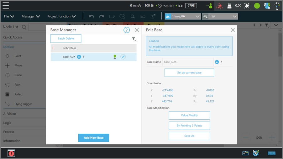
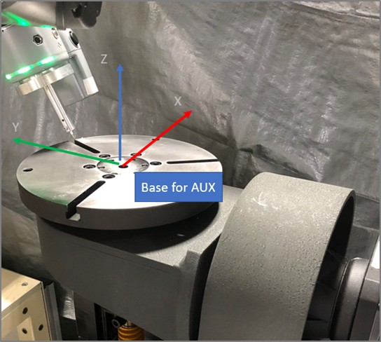
- Create a Base for AUX in TMflow. Edit the coordinate value of this Base with the data in Positioner_Cal.txt/AUXBase.
- By doing this, it will create a base at the center of the rotary plate.
- Make sure that you use correct Base and TCP before teaching the points.
Example of Motion #
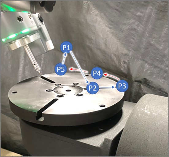
Here is the video for the sample path. We will use this path for tutorial.
- P1: Home point
- P2: Line point
- P3: Line point
- P4, P5: Circle points
- P1: Home point
Preparation #
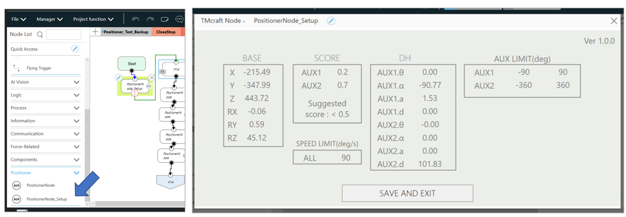
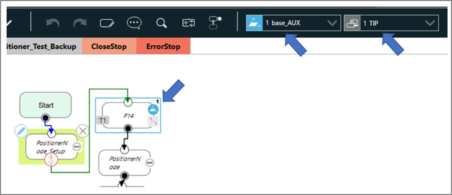
- Drag a PositionNode_Setup to the beginning of the TMflow project. Then edit it. The calibration result (from the Positioner Toolbar) will be loaded automatically. Hit SAVE to apply the result. This setup node is necessary for every TMflow project that using AUX.
- Select correct Base and TCP, then drag a POINT node as a starting point(P1). This node ensures that the Base and TCP are enabled correctly.
Move AUX and Teach Points #
- On the Positioner toolbar, jog AUX to desired position. For example, [AUX1, AUX2] = [0, 0]. Then guide the TCP to P2. Then drag a PositionerNode after the Point node.
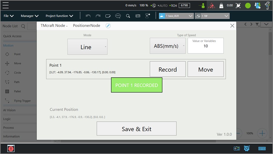
- In the PositionerNode, hit Record to save current position of the TCP and AUX. Then hit Save & Exit.
- Jog the AUX to [-10, 20] then guide the TCP to P3. Drag a new PositionerNode and follow previous steps to record this position, P3.
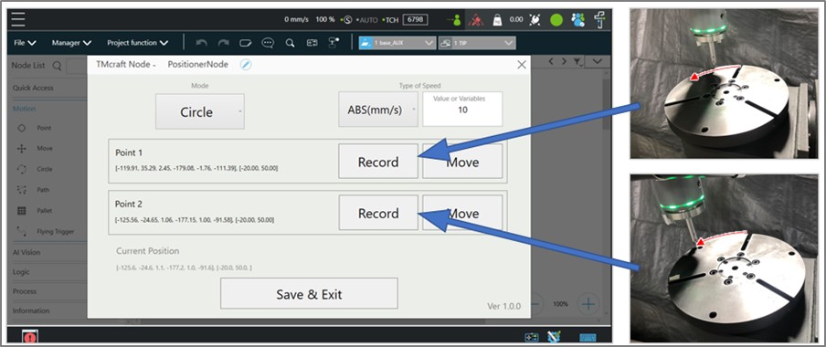
- Jog the AUX to [-20, 50]. Drag a new PositionerNode and change the Mode to Circle. Guide the TCP to P4 and P5 and hit Record The arc will be created on P3 > P4 > P5.
- Drag a GOTO node and assign it to go back to P1.
- Run the TMflow project. You will see the TCP follow the path with synchronized motion on the AUX.
Hints #
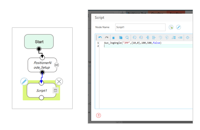
- It is possible to use AUX commands to manipulate the AUX in the SCRIPT node. Move the AUX to designated target for example.
- For the speed in the PositionerNode, it is possible to enter an integer (15mm/s for example) or a variable(int) directly.

Common Q&A #
Could I design an AUX with a different size?
Yes. The calibration procedure accounts for different sizes and configurations. This data will be stored in the calibration file (DH parameters).
Does TM provide the hardware for AUX?
No. The AUX must be provided by a 3rd-party integrator.
Could I use another brand of servo motor?
Due to the complexity of servo motors, TM currently supports only Yaskawa Sigma-X EtherCAT models. More models for different brands are under investigation. Might support other brands in the future.
Does TM also support a linear track?
The linear track function is under development and is not yet supported.
Why does the AUX vibrate or having noise during use?
Perform motor tuning first. Refer to the servo motor’s manual for instructions.
Could I use the AUX with cobot in collaborative mode without fence?
Since the external AUX cannot meet collaborative safety standards, developers must evaluate the arm’s operation mode in this case, which may require equipment such as safety fences.

