Examples are valid for:
TMflow Software version: 2.16.1500 or above.
TM Robot Hardware version: HW5.0 or above.
Note that older or newer software versions may have different results.
Overview #
The automatic configure acceleration tool is designed to adjust speed and acceleration for different distances by robot system. This eliminates the need to set multiple variables and nodes to accommodate speed configurations for varying distances. The system automatically selects the corresponding speed and acceleration time from the acceleration table based on the point-to-point distance. Additionally, a set of default values is provided to meet the requirements of most pick & place tasks.
Application better in following scenarios #
- In pick & place tasks, when approaching the gripping or placing points, to prevent excessive shaking caused by inertia, it is common to reduce the movement speed and acceleration when reaching the target point. This is typically achieved by manually determining the distance and then setting the appropriate speed and acceleration values.
- Manually adjusting speed and acceleration to optimize cycle time requires iterative testing for finding the optimal solution.
How to use? #
The Acceleration Table is in the Project Function.
Acceleration Table offers a total of five configuration settings, each consisting of point-to-point distance range, speed range, and acceleration time range. The first and last configuration settings are mandatory to be enabled.
-
- Distance Min (mm): The minimum distance. It is directly determined based on the maximum distance of the previous group to ensure continuity in the distance ranges for all groups.
- Distance Max (mm): The maximum distance. Users can set this value by self. However, if the actual point-to-point distance exceeds the maximum distance of the last configuration setting, the speed and acceleration time will be configured according to the maximum distance of the last configuration setting.
- Speed1 (%): Linear interpolation speed. Effective when linear interpolation is enabled. Users can adjust Speed1 and Speed2 to configure speeds for point-to-point distances.
- Speed2 (%): Speed configuration. If linear interpolation is not enabled, the setting value of Speed1 will be forcibly synchronized with Speed2.
- Time to Top Speed1 (ms): Linear interpolation acceleration time. Effective when linear interpolation is enabled. It will be automatically calculated and input based on the setting of Time to Top Speed 2, and cannot be modified.
- Time to Top Speed2 (ms): Time to reach top speed. If system default acceleration is disabled, users can set this value by self.
There are two selectable functions: Linear Interpolation and System Default Acceleration, which provide flexibility and customization.
-
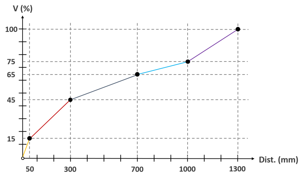
- Linear Interpolation: Default setting is enabled. Enabled means that the speed and acceleration times for this configuration group will linearly vary with different point-to-point distances, as shown in the diagram.
Note: This feature does not dynamically adjust with changes in the moving distance but configures based on the initial point-to-point distance.
If disabled, the speed and acceleration times for this group will remain consistent within the set point-to-point distance range.
-
- System Default Acceleration: Default setting is enabled. It will automatically adjust the Time to Top Speed corresponding to the set speed settings based on the system’s default acceleration curve. The same acceleration curve is maintained for different speed settings.
If you wish to use different acceleration settings for various distance ranges, you can disable the default system acceleration and manually change the setting value for Time to Top Speed2. This will result in different acceleration curves.
In the motion settings of each motion node (except for Path Nodes), the speed setting option is set to use the acceleration table by default.


