Introduction #
This Application White Paper (APPWP) is a guide to help users when using EtherNet/IP connection with Techman Robot. EtherNet/IP is an industrial Ethernet protocol developed by Rockwell Automation, managed by ODVA. IP is an abbreviation of Industrial Protocol. EtherNet/IP is based on TCP/IP communication protocol, compatible with general IT networks. It can be used in process control and other automation applications, such as factory automation (FA).
Users can:
- Easily use EtherNet/IP certified PLC to connect with TM robots as an EtherNet/IP slave in order to access the robot’s I/O and send commands to the robot.
- Choose Profinet or EtherNet/IP on TMflow setting page according to their requirements.
The overall application involves two TM robots serve as EtherNet/IP slaves and PLC serves as the master. A conveyor delivers an object to the TM robot and executes related actions. This process demonstrates a scenario of a factory production line. The details of the all-in-one process are introduced in this APPWP. Users are able to implement EtherNet/IP functions by using TM communication protocol.

Since EtherNet/IP is widely used in North America, Techman Robot has implemented EtherNet/IP protocol for users. Users should note that Techman Robot has no built-in EtherNet/IP hardware. If users need to utilize EtherNet/IP, you can purchase this product additionally, contact any TM sales member/agent/partner.
System Configuration #
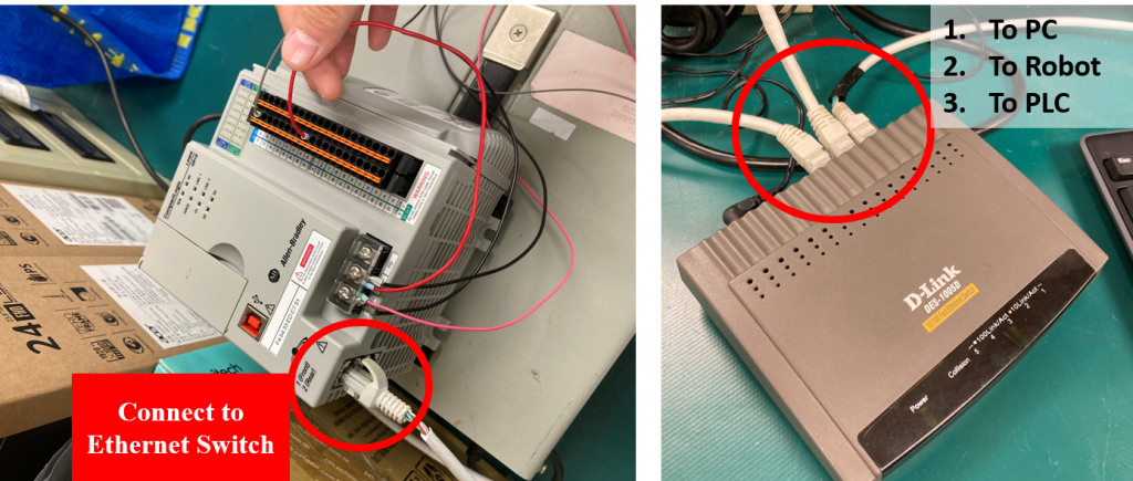
The general hardware and software setup can be found here. In this application, users are required to prepare an Ethernet Switch and connect the ethernet cable as the figure below.
At the Ethernet Switch, 3 connections are made to PC, robot, PLC respectively. It is an easier way to connect PLC, robot, PC, or other slaves, use an Ethernet switch to connect all devices, and allow the IPs in the same subnet.
Detail procedures are provided in this AWP, a step-by-step guide of connecting Techman Robot with Rockwell PLC via EtherNet/IP will be described in the following sections.
The main devices are two TM Robots and a programmable logic controller (PLC), and the programming software is installed on the PC. The configuration of EtherNet/IP drivers can be found here.
Hardware Configuration #
- PLC: Rockwell-1769‐L24ER‐QB1B
- PLC Programing Software: Studio5000
- Robot A (EtherNet/IP Slave)
-
- HMI Version: 1.82.1100
- Robot Model: TM14MX-1100
- Control Box: Mobile series control box
- Robot B (EtherNet/IP Slave)
-
- HMI Version: 1.82.1200
- Robot Model: TM-14-1100
- Control Box: Medium & heavy payload series standard control box
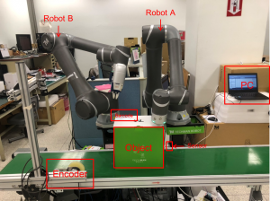
According to the diagram above, the hardware includes a conveyor, which is run by a motor, with a sensor fixed in the middle of the conveyer. The motor and the sensor are connected to PLC via I/O. There are two Techman Robots that are settled beside the conveyer. One robot will scan the barcode of the object; the other robot will move away from the object after scanning the barcode. Both Techman Robots are connected to PLC via EtherNet/IP.
The PC has PLC programming software installed – Studio 5000 – and the user can use this software to program the ladder diagram. The PC is connected to the PLC via Ethernet. The object is a package box that has a barcode on it.
Ethernet Configuration #
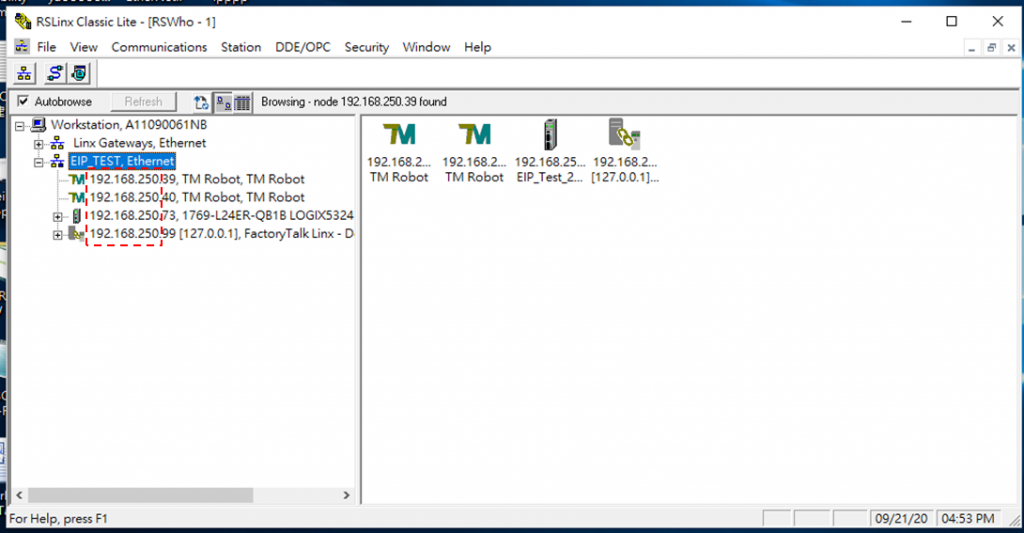
Four devices are using Ethernet connections. There are PLC, Robot A, Robot B, and PC because the PLC device that we used doesn’t have enough protocol, there is an additional switch to connect with those devices. Every device should be set in the same domain (255.255.255.0). As shown in this example, the IP of all devices should be set below 192.168.250.xx.
IP Configuration (an example)
- Robot A: 192.168.250.39
- Robot B: 192.168.250.40
- PLC: 192. 168.250.73
- Notebook/PC: 192. 168.250.99
Procedures #
Step #1: Users start the TMflow project of Robot A and Robot B and put the Object on the conveyor.
Remark: How do we create a simple TMflow project and implement ethernet/ip functions?
Step #2: Robot A will send a signal to PLC, and then PLC commands the conveyor belt to start.
Step #3: When the object reaches the sensor, the sensor will send a signal to PLC, and then PLC will stop the conveyor belt.
Step #4: PLC commands Robot A to move to the left side of the object and sends a signal to PLC to simulate gripping the object
Step #5: The PLC commands Robot B to move to the left side of the object to scan the barcode.
Step #6: After Robot A and Robot B complete their jobs, they send signals to PLC, and then PLC will move the conveyor.
Step #7: In the end, the PC displays the barcode value.
Demo Video #
The demonstration video shows the procedures of the application.


